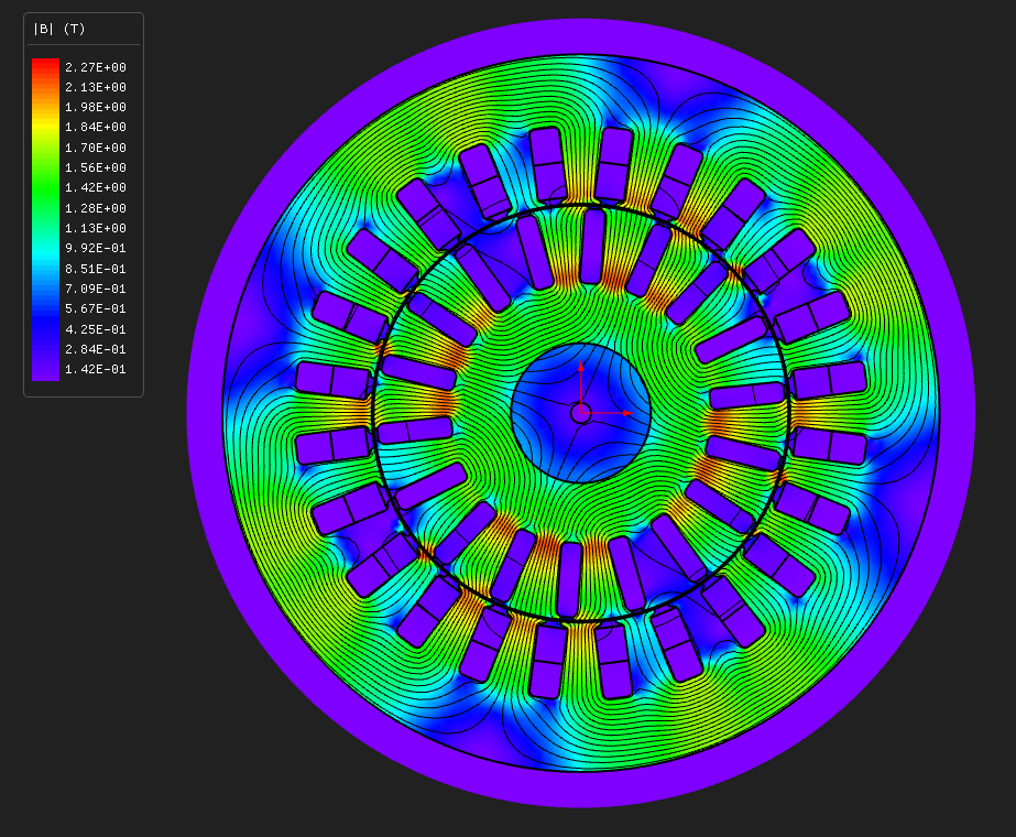
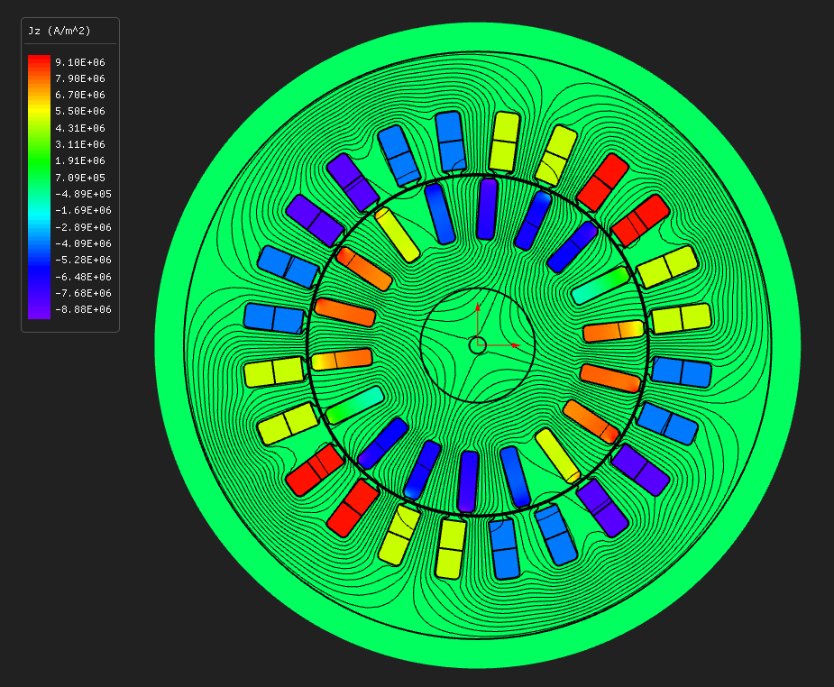
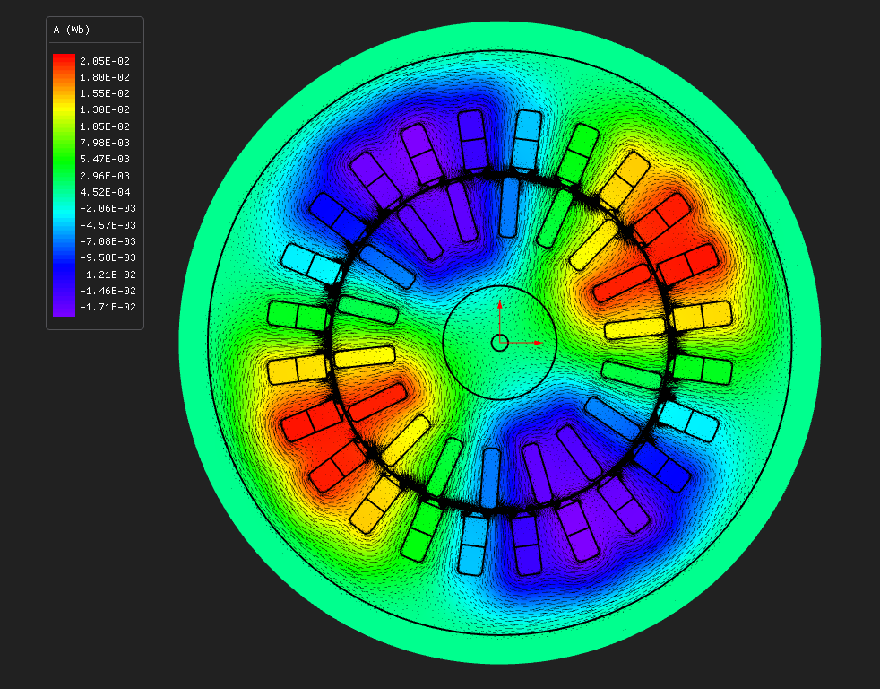
E08 — 24-slot / 18-bar 4-pole induction machine with skewed rotor bars
IM · Trapezoidal Tooth · 24 slots / 4 poles · 10.677 N·m at 1425 rpm · 70.2 % efficient · 9698 nodes · 618 s
What you need to run it: the Python API, the Machines module and Core Pro. Opening the model and reading results that are already there never requires a licence. Core Pro covers the rotor-bar skew, Crank-Nicolson time integration and the time-harmonic extraction - which is most of what this example is for.
At a glance
| Quantity | Value | Unit |
|---|---|---|
| Speed | 1425 | rpm |
| Electrical frequency | 50.0 | Hz |
| Slip | 0.050 | — |
| Average torque | 10.677 | N·m |
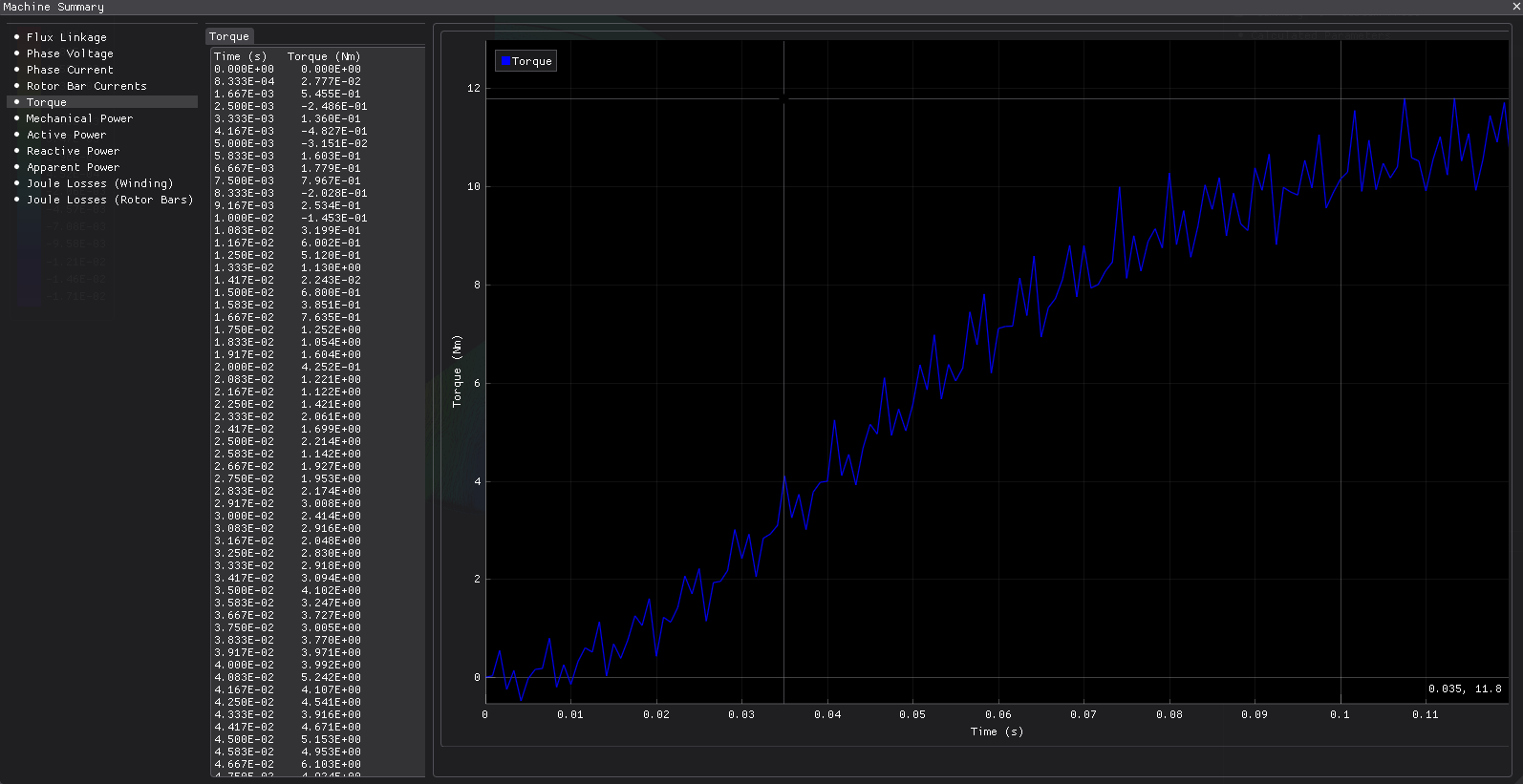
| Torque ripple | 17.8 | % |
| Mechanical power | 1.593 | kW |
| Efficiency | 70.24 | % |
| Power factor | 0.589 | — |
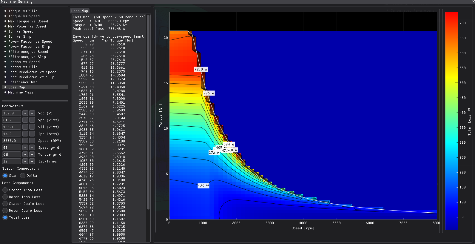
| Total losses | 675.1 | W |
| Max B, stator tooth | 1.754 | T |
| Mesh | 9698 nodes, 17715 elements, P1 | — |
| Wall time, end to end | 618 | s |
The induction machine with everything switched on that E07 deliberately left off:
- skewed rotor bars, solved as three axial slices coupled to each other;
- the deep-bar effect — eddy currents inside the bars themselves, not just the resistance the circuit sees;
- Crank-Nicolson time integration instead of backward Euler;
- trapezoidal teeth on both stator and rotor.
Same frame as E07 — 120 mm outside, 90 mm stack, four poles, 50 Hz — so the two are directly comparable machine for machine.
This is the slowest model in the set: roughly twenty minutes end to end. Skew multiplies the work by the slice count, and the run needs six electrical periods for the rotor to settle.
Why this one solves half the machine
E07 gets away with a quarter. This machine cannot do better than a half, whatever you do to it, and the bar count is why.
The symmetry sector is the greatest common divisor of coils per phase, poles and rotor bars. Eighteen bars is 2 × 9, so it carries a single factor of two. Any even pole count already shares that factor, and so does any layer count, so the divisor is 2 for every combination — a half machine, always. E07's 28 bars carries two factors of two, and a double-layer winding brings a third, which is what lets it reach a quarter.
Twelve slots and nine bars over 180°, and because the sector holds two poles the cut is closed periodically — the opposite of E07's anti-periodic cut.
The design
| Layer | Radii (mm) | Set by |
|---|---|---|
| shaft bore | 1.700 | derived from rotor shaftThickness 10 |
| rotor shaft | 1.7 → 11.7 | shaftThickness 10 |
| rotor yoke | 11.7 → 21.7 | coreThickness 10 |
| rotor bars | 21.7 → 34.7 | slotDepth 13, slotWidth 3.5, 18 bars |
| air gap | 34.7 → 35.0 | airGap 0.3 |
| stator bore | 35.000 | ID 70 |
| slot bottom | 48.000 | slotDepth 13, slotWidth 3.0, 24 slots |
| stator OD | 60.000 | OD 120, back iron 12 |
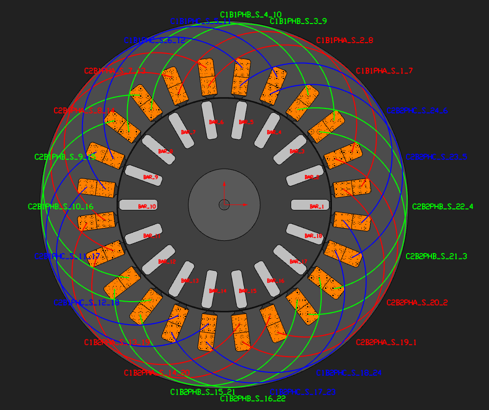
The rotor yoke is thinner than E07's to give radius to a deeper bar. Depth over width is 3.7 here against E07's 2.5, and the bar is elongated on purpose — a deep bar is what makes the skin effect worth modelling.
Skew is one stator slot pitch, 15° mechanical, which is the classical choice, over three slices. Three is the smallest count that represents a linear skew rather than a single straight cut.
Winding and materials
| Stator core and rotor yoke | M-19 Steel, nonlinear BH |
| Rotor shaft | 1020_steel |
| Rotor bars | conductivity 2.4 × 10⁷ S/m on the region, same as E07 |
| Winding | three-phase distributed double layer, q = 2, full pitch |
| Turns per coil | 26 |
| Slot fill | 0.42 |
| Parallel branches | 2 |
| End winding | 20 mm extension |
Two parallel branches against E07's four is the main reason this run's current density and copper losses are higher at the same 20 A excitation — fewer parallel paths means more current per conductor. It keeps the winding simple against a 180° sector rather than a 90° one. If you want the cleanest possible comparison of skew and deep-bar physics against E07, set the branch count to 4 and re-run.
Iron loss uses the same fitted coefficients as E07, so the two machines' iron losses are directly comparable.
Operating point
| Excitation | 20 A peak, slip 0.05, shaft speed 1425 rpm |
| Supply | 50 Hz, 1500 rpm synchronous |
| Eddy currents | on in the rotor bars, off everywhere else |
| Skew | 15° mechanical over 3 slices, solved together |
| Time integration | Crank-Nicolson, with two backward-Euler startup steps |
| Extraction | time-harmonic method, locked-rotor stage at 12.5 Hz |
| Window solved | six electrical periods, 48 steps each |
| Elements | first order, deliberately |
The locked-rotor stage is where the deep bar shows up. Run at a real, non-zero rotor frequency — a quarter of line frequency here — a bar this deep has already started to leave its DC regime, so the extracted rotor resistance is an AC resistance rather than the geometric one. That is the reason for choosing the time-harmonic extraction method on this machine.
First-order elements on purpose. Skew at second order costs roughly eleven times the wall time per step, and this run is already the most expensive one here at first order.
Running it
Open im_24s18r_trap_skew.nbl and press Solve, and leave it running. The solved field is not
shipped: three coupled slices over 288 steps write a 644 MB file.
From Python:
python build_im_24s18r_trap_skew.py                 # build, solve, analyse, report
python build_im_24s18r_trap_skew.py --no-solve      # geometry and mesh only
python build_im_24s18r_trap_skew.py --no-skew       # the unskewed control run
Skew and Crank-Nicolson both need a Core Pro licence; the machine itself does not.
What to look at
What the skew costs and what it buys. The classical skew factor for one slot pitch is
0.9886, so less than half a per cent off the fundamental flux linkage. Almost anything else that
moves between the skewed and unskewed runs is the slot-harmonic suppression that skew is
actually for. Run --no-skew and compare the torque ripple directly — that comparison is the
most useful thing in this model.
How the slices are solved. They are not three independent runs averaged afterwards. One conductor threads all three slices, so they share a current, and the solver assembles them into one system with a single circuit block. That is what makes a skewed cage more expensive than three times a single slice, and it is also what makes it right.
Crank-Nicolson against backward Euler. Second-order accuracy in time for the same step count. On a smooth transient it lets you take fewer, larger steps for the same error; near a switching discontinuity it can ring, which is why the run starts with two backward-Euler steps before switching over.
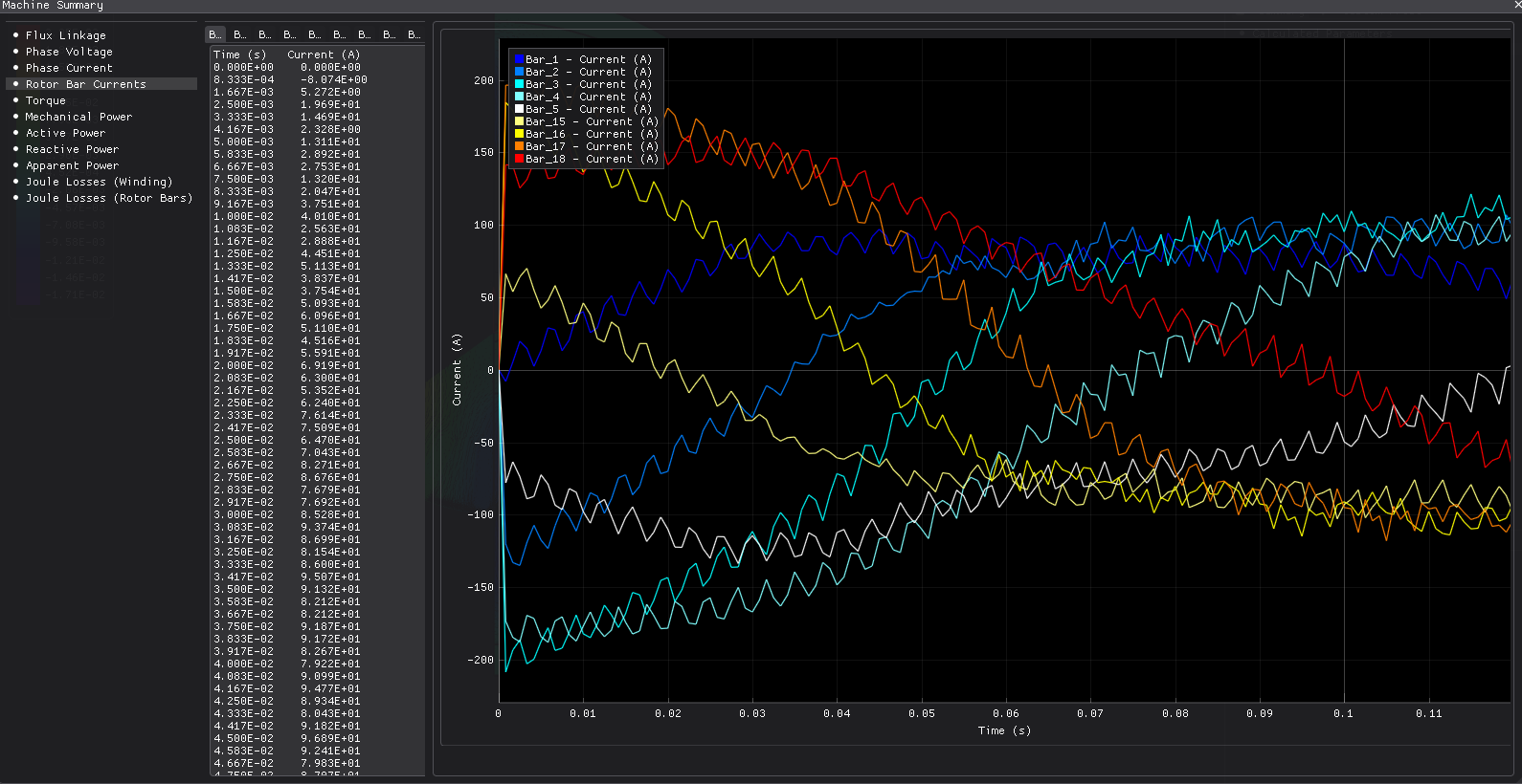
The bar current profile is in rotor_bar_current.csv. Compare it with E07's: a skewed
rotor's bars carry a noticeably less even distribution, and the bar sitting against the periodic
cut is the low outlier.
Open questions in this run
Three things in this model are reported as they came out rather than tidied, and they are worth knowing before you lean on the numbers.
The bar current spread is wide — about three to one between the lowest and highest bar, against roughly two and a half to one on E07. The low bar is the one against the periodic sector cut. That is plausibly a genuine consequence of a periodically cut, skewed rotor, since that bar's three slices see a different angular relationship to the travelling field than a bar deep inside the sector. It has not been confirmed against an independent calculation.
The implied slip runs above the commanded one. Bar loss divided by airgap power should track the slip you asked for; here it comes out higher. The direction is what the deep-bar effect should do — a higher effective AC bar resistance — but the size of it has not been cross-checked against an independent skin-effect calculation.
The power balance closes to about 5 % rather than the fraction of a per cent the PM examples manage. It is likely the same root cause as the item above: something in how per-slice bar loss and mechanical power are summed against each other.
None of these is run-to-run noise — the model is deterministic and rebuilds identically. If your
work depends on absolute rotor loss on a skewed cage, run the --no-skew and
eddy-currents-off comparisons below and treat the differences as the result rather than any
single absolute figure.
Try this next
--no-skew— the same machine with the twist removed. This is the comparison the example exists for.- Turn the bar eddy currents off with everything else unchanged. That isolates the deep-bar contribution to the extracted rotor resistance, and it is the most direct way to chase the implied-slip question above.
- Set parallel branches to 4 to match E07, which removes the winding difference and leaves only the skew and deep-bar physics between the two machines.
- Make the bar shallower, closer to E07's proportions, and watch the deep-bar effect fade out of the extracted resistance.
About these numbers
The dimensions are invented but plausible: a four-pole 50 Hz machine of roughly 1 kW on the same frame as E07, not a copy of a published design. The validated induction machine lives in the validation dossier, and that is where an accuracy question belongs.
More from this run