Assumptions
This case study simulates the eddy currents induced in a hollow conductive cylinder when exposed to a time-varying magnetic field generated by an external current layer. The simulation is performed in 2D using the transient magnetic vector potential formulation. The cylinder is assumed to be made of copper with known electrical conductivity and magnetic permeability. The external 6-pole current layer produces a sinusoidal magnetic field with a specified frequency and amplitude.
Parameters
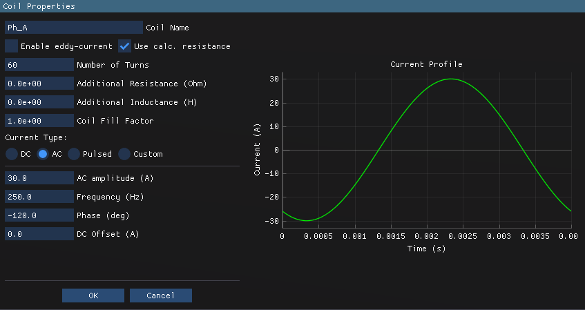
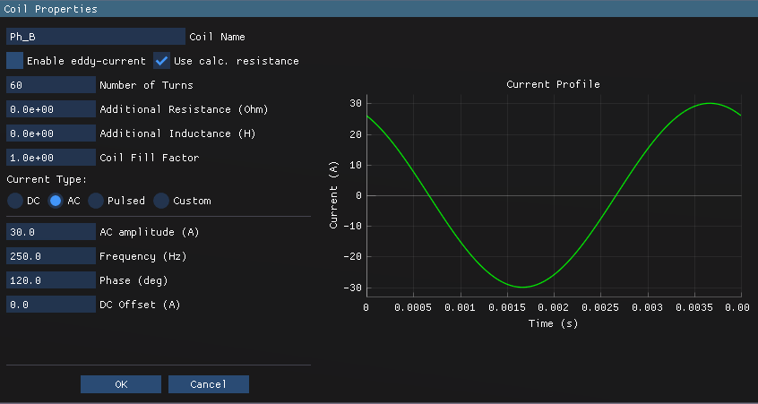
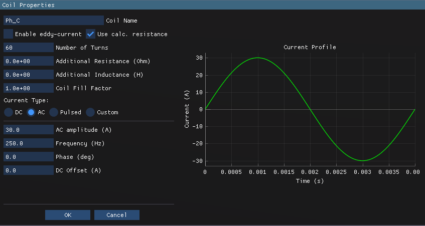
- 6-pole current layer is represented via 3-phase coils: 60 turns per phase, current amplitude: 30 A, frequency: 250 Hz
- Model axial length: 100 mm
- Copper cylinder dimensions: Inner radius = 38 mm, Outer radius = 49.5 mm, Length = 100 mm
- The copper cylinder is stationary and centered within the air region.
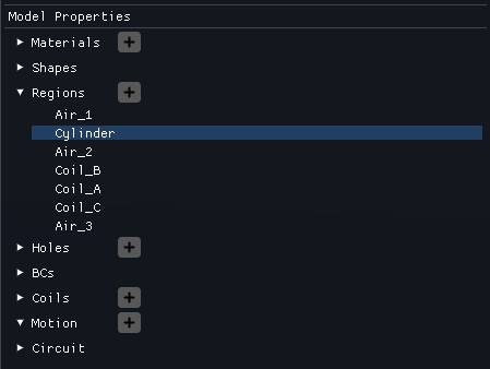
Regions
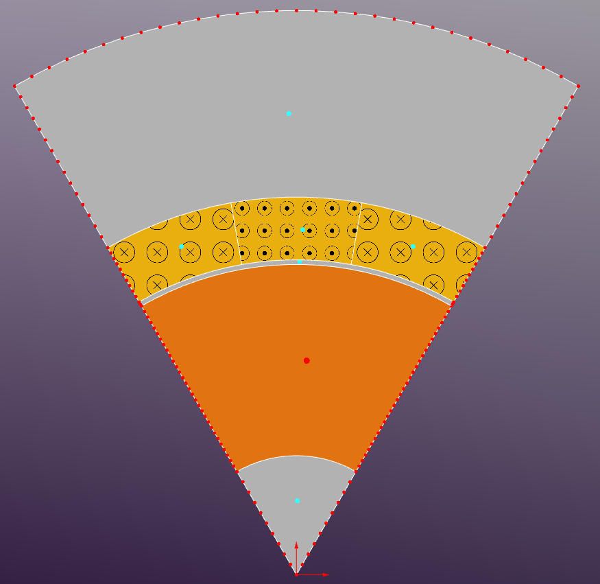
The geometry is divided into several regions representing different materials:
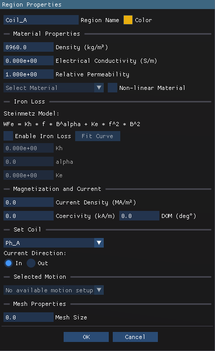
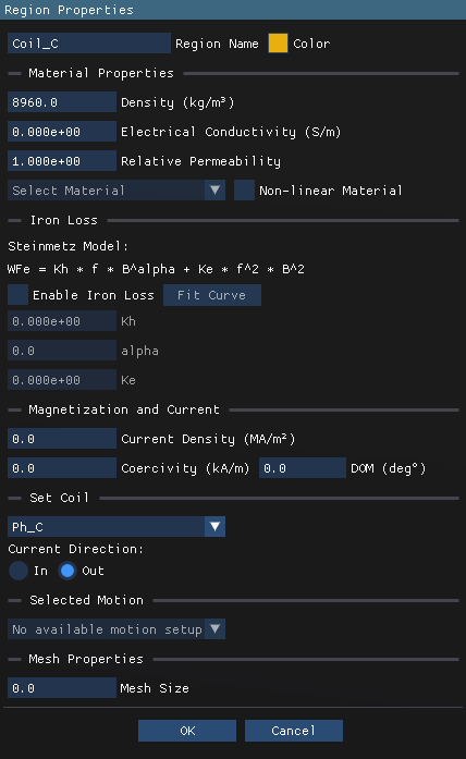
- Current Layer: Region containing the 3-phase stranded coils (eddy-current effect is disabled in this region)
- Air: Surrounding air region (non-conductive)
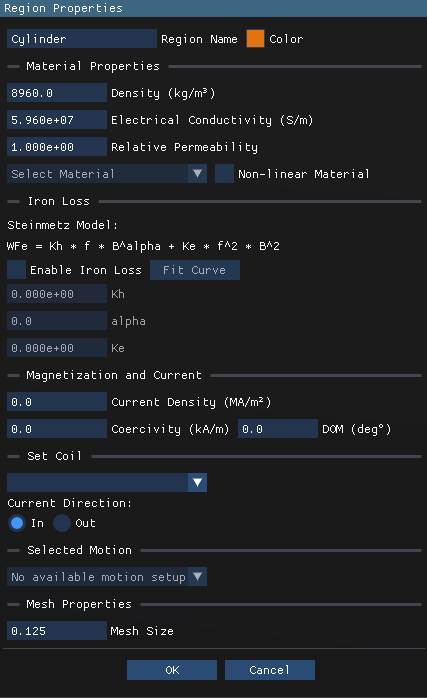
- Copper Cylinder: Conductive region where eddy currents are induced (electrical conductivity is set to 5.96e7 S/m)
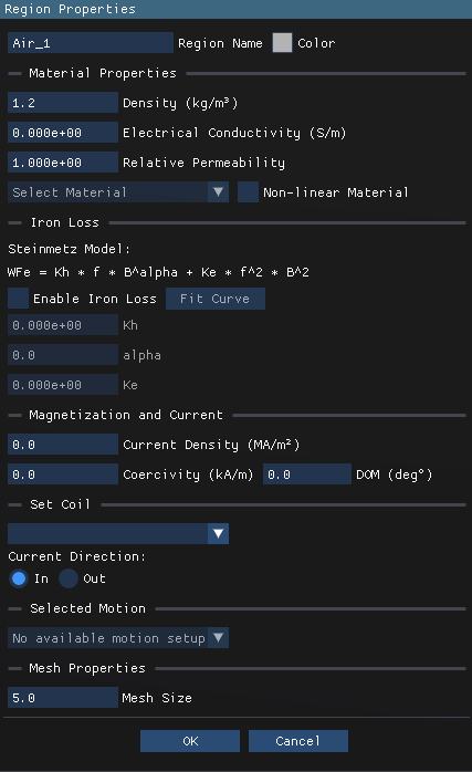
Region Properties
The region properties are defined as follows:

Boundary Conditions
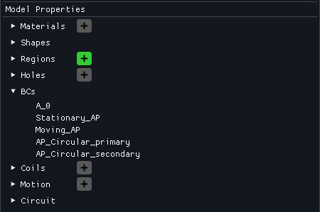
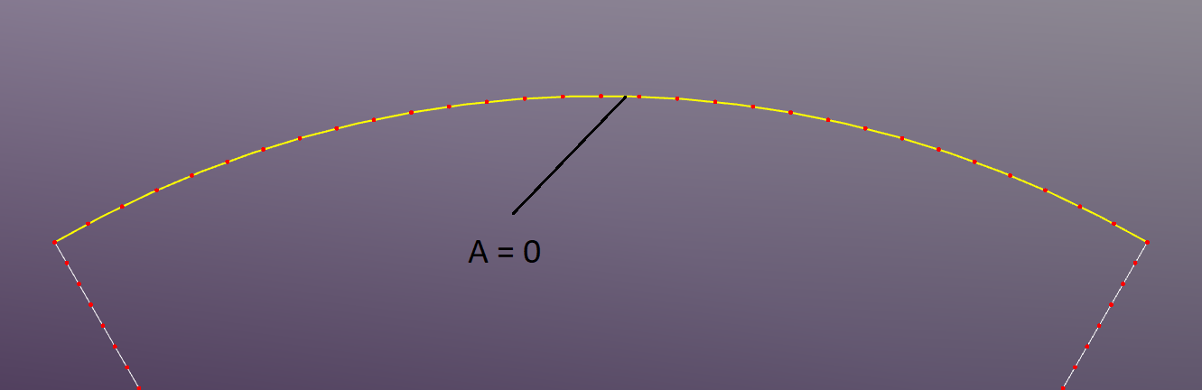
The outer boundary of the model is set as a Dirichlet boundary condition with a fixed magnetic potential of zero.
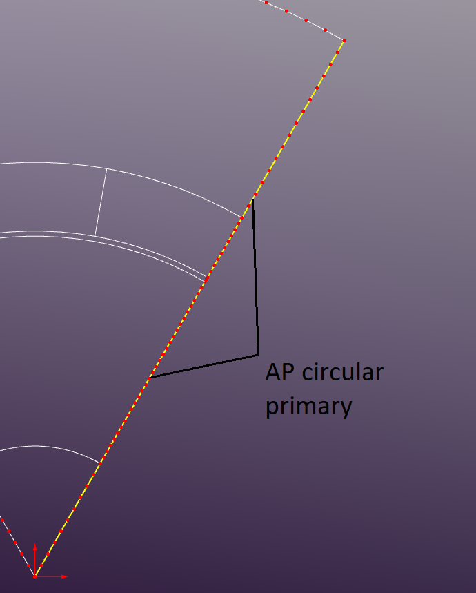
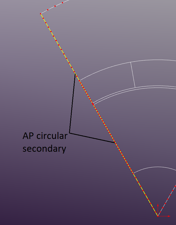
"Anti-Periodic Circular" BCs are applied to the left and right edges of the 60-degree sector to simulate the full 360-degree geometry.
Coils
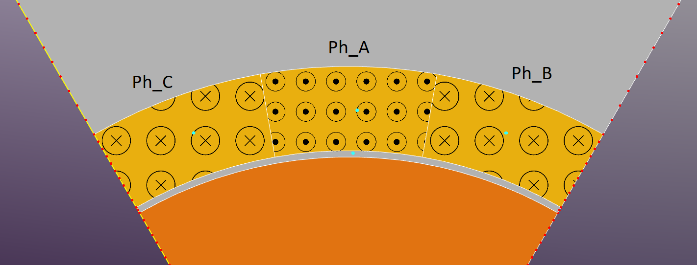
The current layer is represented using three separate coils corresponding to the three phases (Ph_A, Ph_B, Ph_C) of the 6-pole winding configuration.
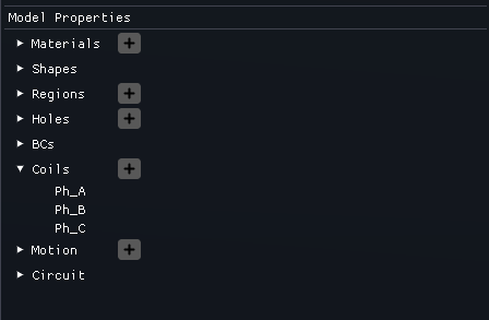
The coil setup is illustrated below:
The simulation is run in current-driven mode where the coil currents are specified directly. The phase currents are defined to produce a balanced 3-phase system with a peak current of 30 A.
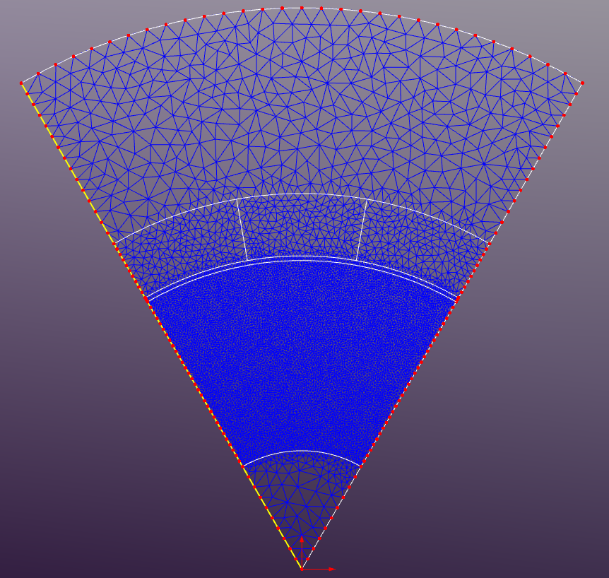
Meshing
The default mesh settings are used with a maximum element size of 1mm2
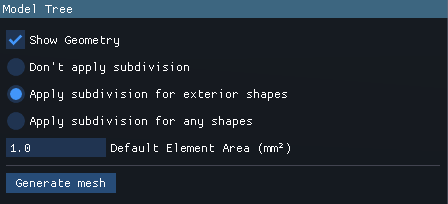
If the mesh size set to 0 in the Region Properties then the default mesh size will be applied to that region. The elements size varys from 0.125 mm in the copper cylinder region to 5 mm in Air_1 and Air_3 regions.
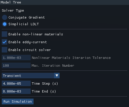
Results
SLDLT solver is used to perform the transient simulation over a time period of 8e-3 seconds with a time step of 4e-5 seconds (200 time steps). The solver settings are shown below:
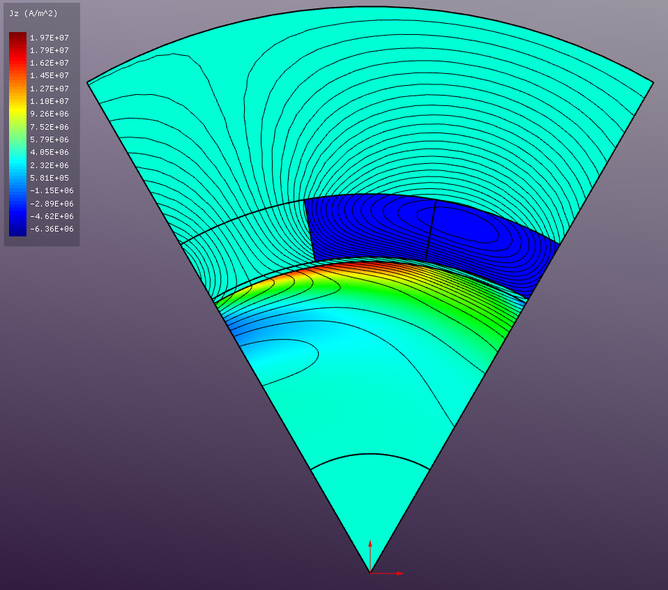
An animation of the induced eddy current density distribution in the copper cylinder during the simulation time is shown below.
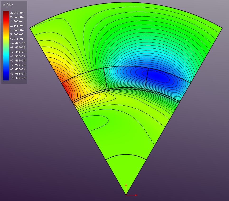
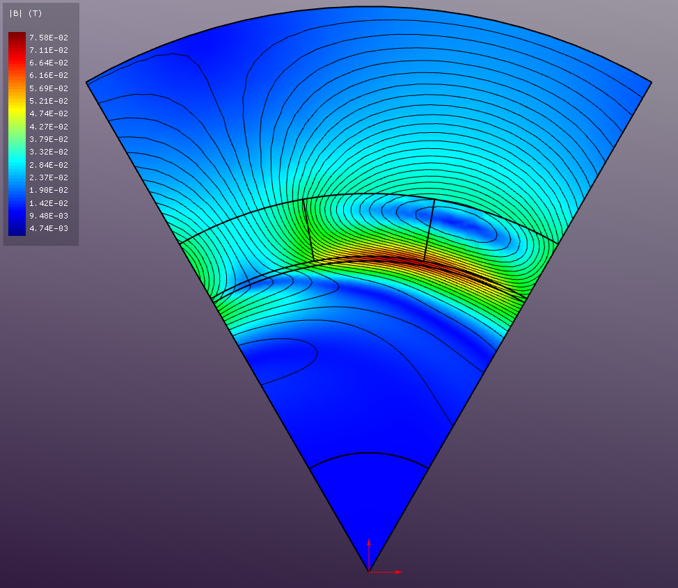
Instantaneous field distributions are shown below:
Vector Magnetic Potential (A)
Absolute Magnetic Flux Density (B)
Current Density (J)