Assumptions
This case study simulates a 2D transient electromagnetic analysis of a three-phase squirrel-cage induction motor (IM) using Nabla. The simulation captures the magnetic field distribution, torque production, and losses during motor startup and steady-state operation.
Parameters
- 3-phase, 8-pole, 26-slot stator and 22-bar squirrel-cage rotor
- Axial length: 100 mm
- Stator outer diameter: 172 mm
- Rotor and stator material: M36 silicon steel
- Operating speed: 5000 RPM
- Frequency: 250 Hz
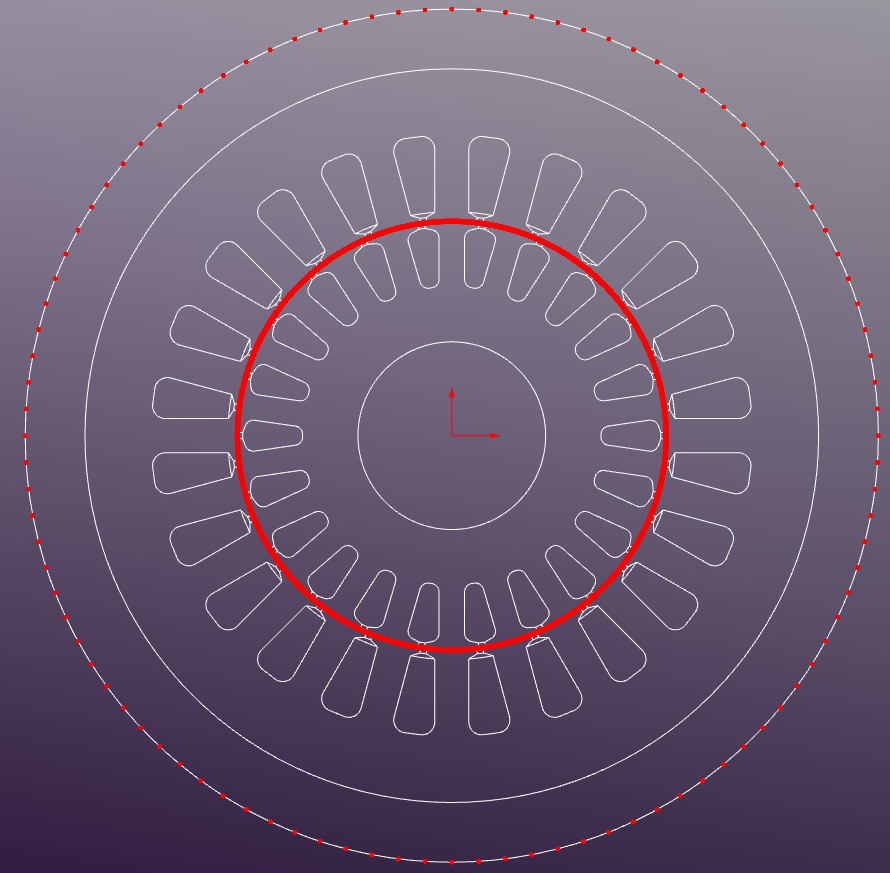
Geometry
The IM geometry is exported from a CAD tool as a DXF file and imported into Nabla.
Regions
The following regions are defined in the model:
- Stator Core: Silicon Steel M-36
- Rotor Core: Silicon Steel M-36
- Air Gap: 0.5mm
- Winding Regions: copper - stranded conductors (eddy-currents disabled)
- Bus Bars: aluminum - solid conductors (eddy-currents enabled)
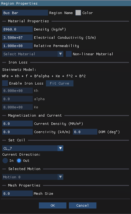
Region Properties
The region properties are defined as follows:
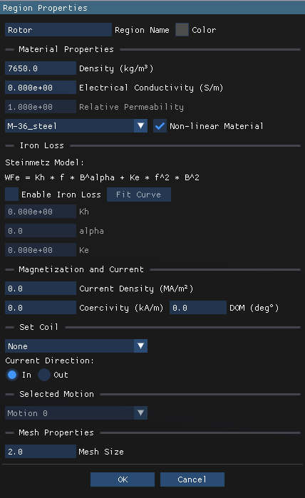


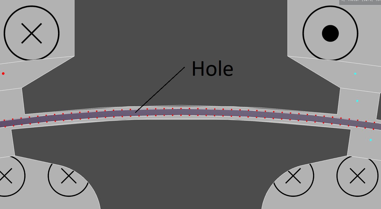
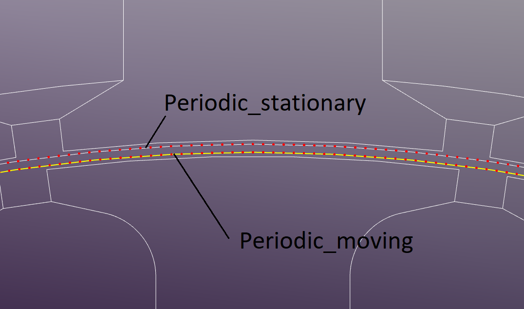
The outer and inner area is set to Air with default properties. The region in the middle of the air gap is defined as hole and is not meshed explicitly. This area is used for sliding mesh implementation.
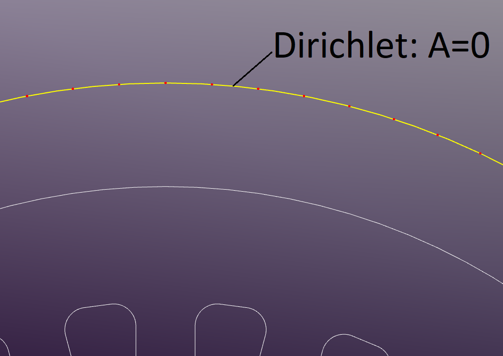
Boundary Conditions
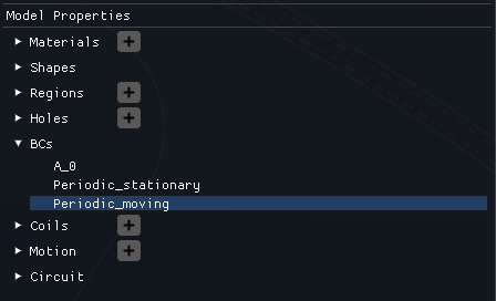
The outer boundary of the model is set as a Dirichlet boundary condition with a fixed magnetic potential of zero.
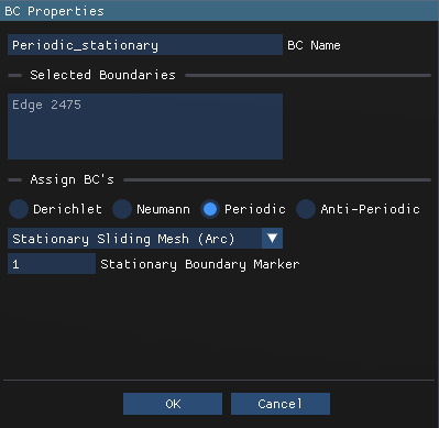
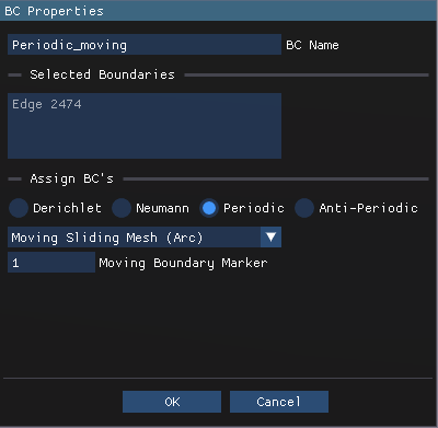
"Periodic Stationary Sliding Mesh" is applied to the stationary side of the sliding band, while "Periodic Moving Sliding Mesh" is applied to the rotating side.
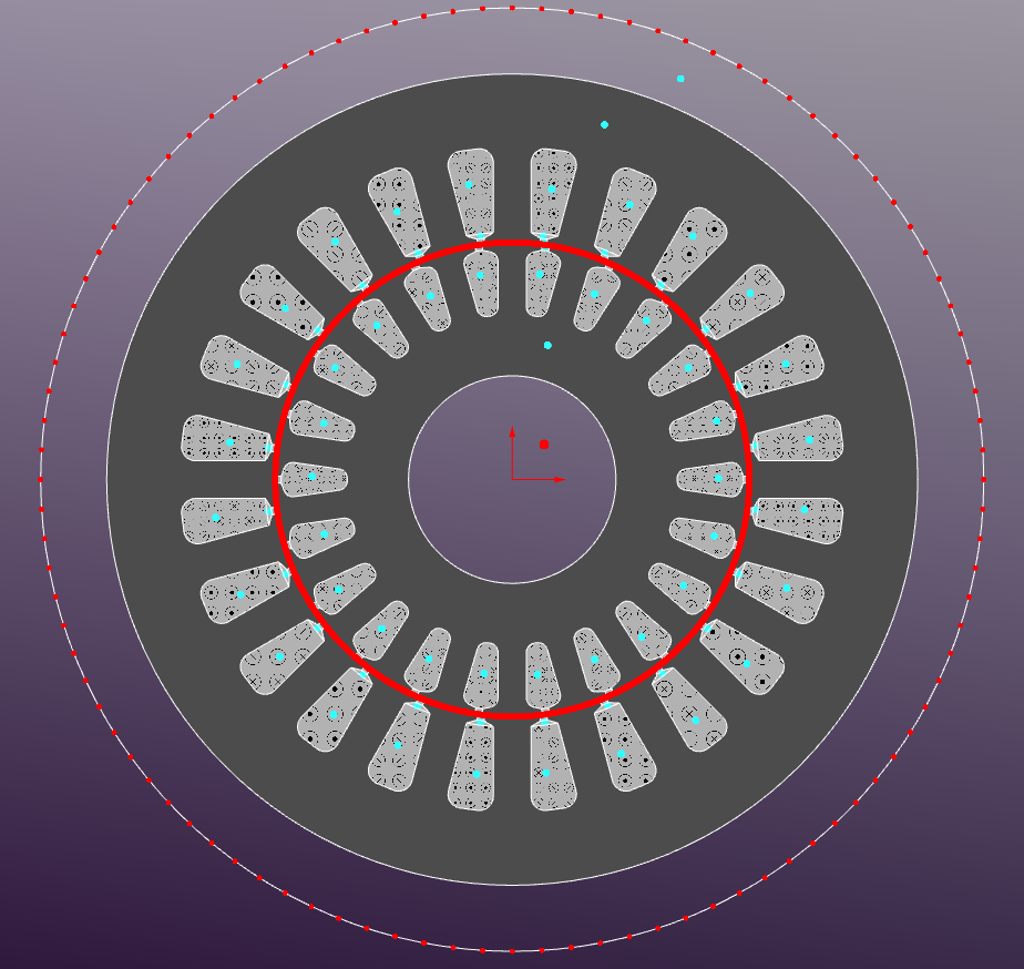
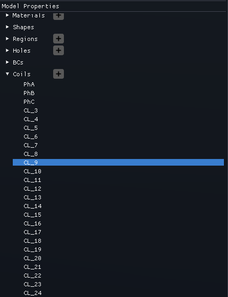
Coils
The Motor Coils are defined in the Model Properties section. The stator winding is devined as a 3-phase distributed winding with 26 slots and single layer configuration: PhA, PhB, and PhC. The bus-bars are defined through the squirrel-cage rotor winding with 22 bars short-circuited at both ends: CL_3, CL_4 .. CL_24
There are two ways to assign coils to regions: in the Region Properties in the corresponding "Set Coil" section or interactively in the main graphical window by selecting the desired region and assigning the coil from the dropdown menu. The coils current direction (highlighted with the corresponding templates) should be set according to the motor's winding configuration (e.g., ABC phase sequence).
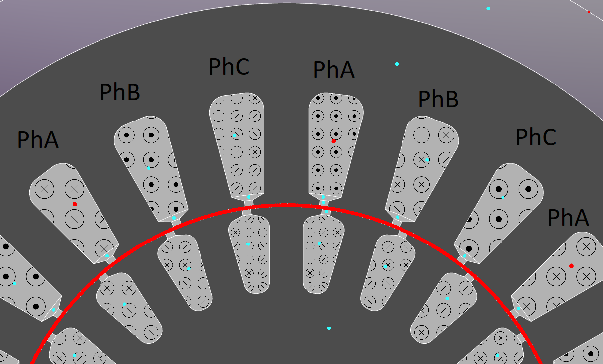
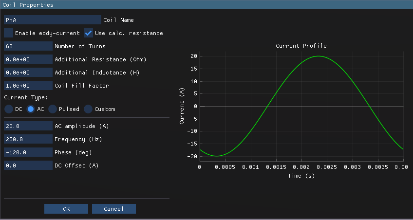
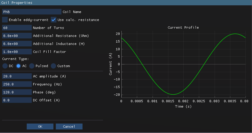
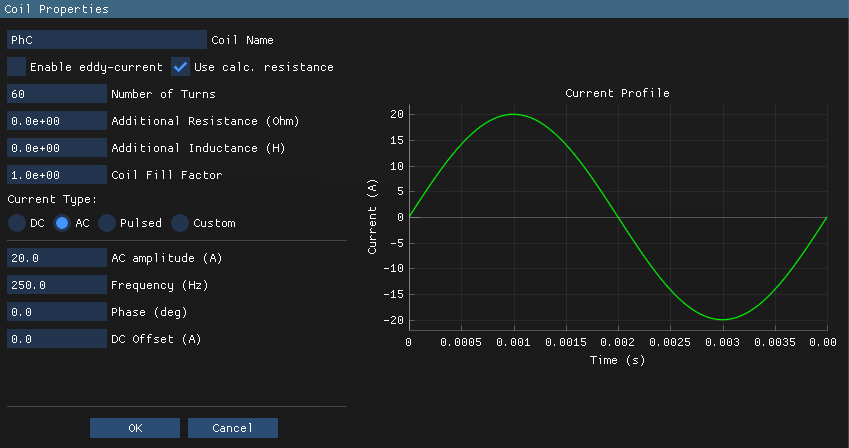
PhA, PhB, and PhC coil properties are shown below: 60 turns per phase, stranded conductor type with disabled eddy-currents.
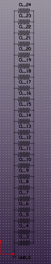
22 bus bars are defined via individual coils (CL_3 to CL_24) with identical properties as shown below. It's a simple coil with one turn.
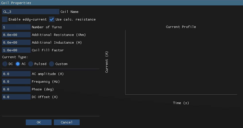
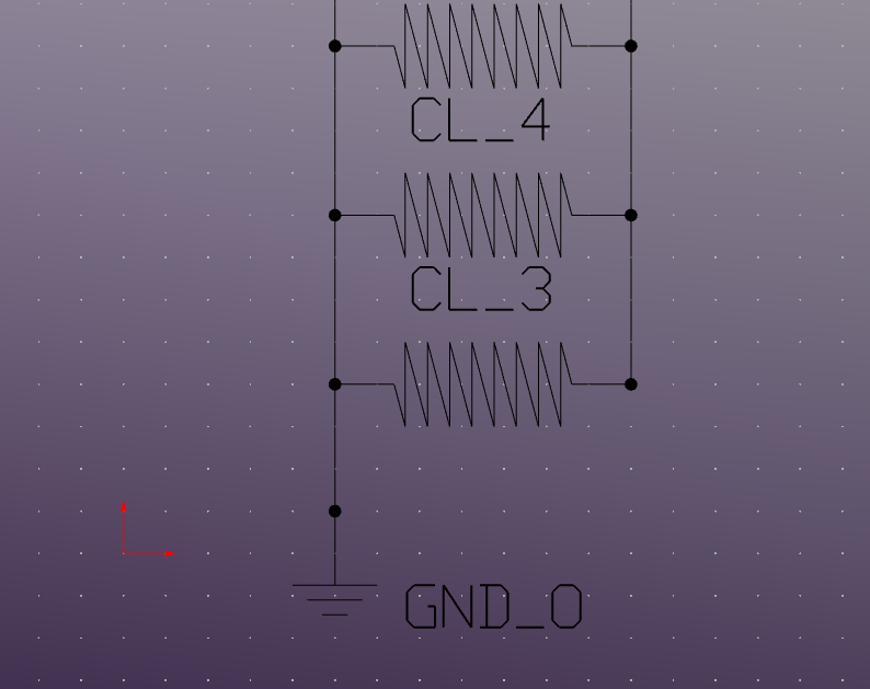
Bus Bars
The bus bars are defined as aluminum solid conductors with enabled eddy-currents to capture the induced currents in the rotor bars during motor operation. To represent the short-circuited end rings, the coils assigned to the bus bars are connected at both ends in the "Cirquit Editor" section.
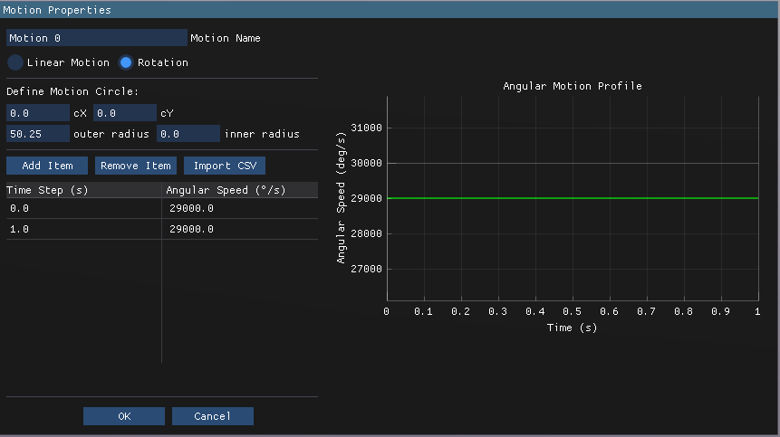
Motion
The motion region is defined as shown below. The rotor is set to rotate at a constant speed with a slip of 0.033: 250Hz electrical frequency and ~483rpm mechanical speed.
Meshing
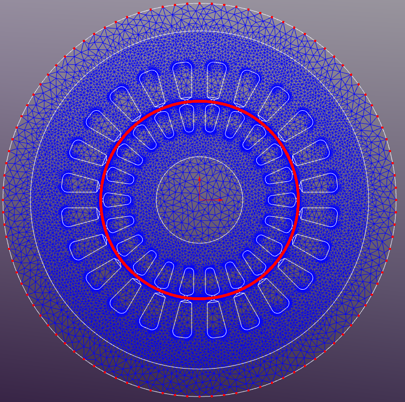
The default mesh settings are used with a maximum element size of 1mm2
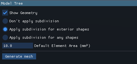
If the mesh size set to 0 in the Region Properties then the default mesh size will be applied to that region. The generated mesh consists of approximately 59310 triangular elements, with finer mesh density in the air gap to capture the high field gradients accurately. An additional subdivision is applied to the sliding band edges to ensure matching mesh on both sides of the sliding interface. "Apply subdivision for exterior shapes" option should be selected in the Mesh Properties to enable this feature.
Solver Properties
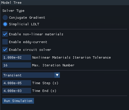
Simplicial LDLT direct solver is used for this simulation. Nonlinear magnetic materials and circuit solver options are enabled as shown below.
Results
The simulation is run for a total time of 0.04 seconds with a time step of 4e-5 seconds, capturing one full electrical cycle at 250 Hz.
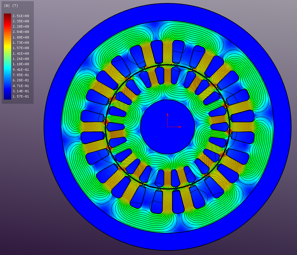
Instantaneous magnetic flux density distribution (during startup).
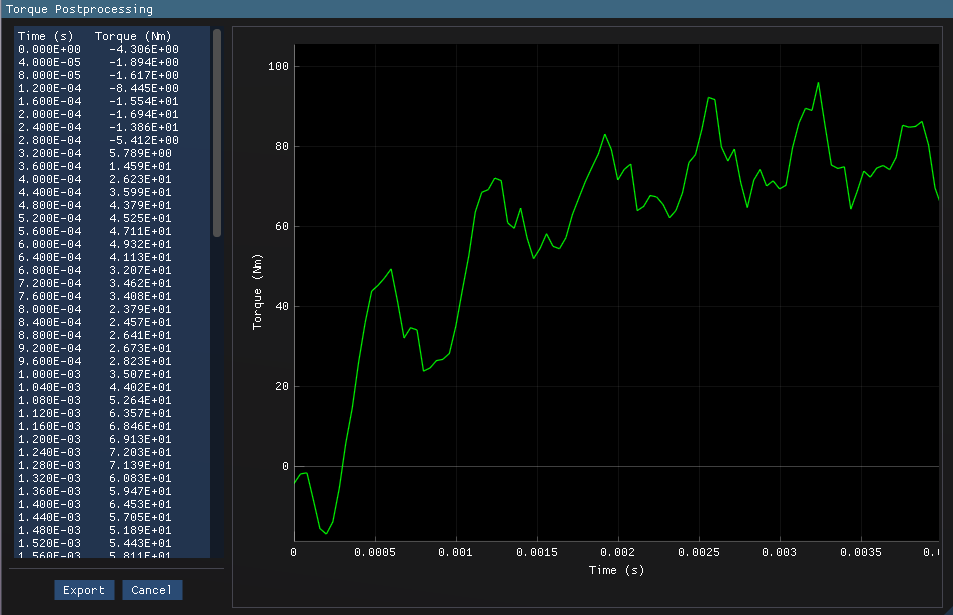
Torque vs time plot during motor startup.
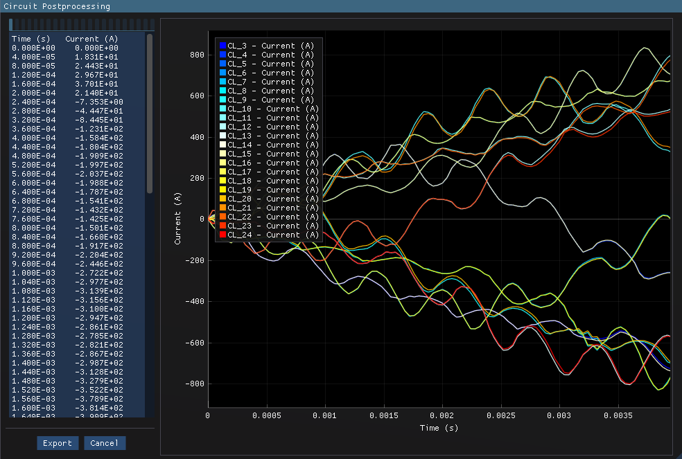
Current in the bus bars vs time plot during motor startup.
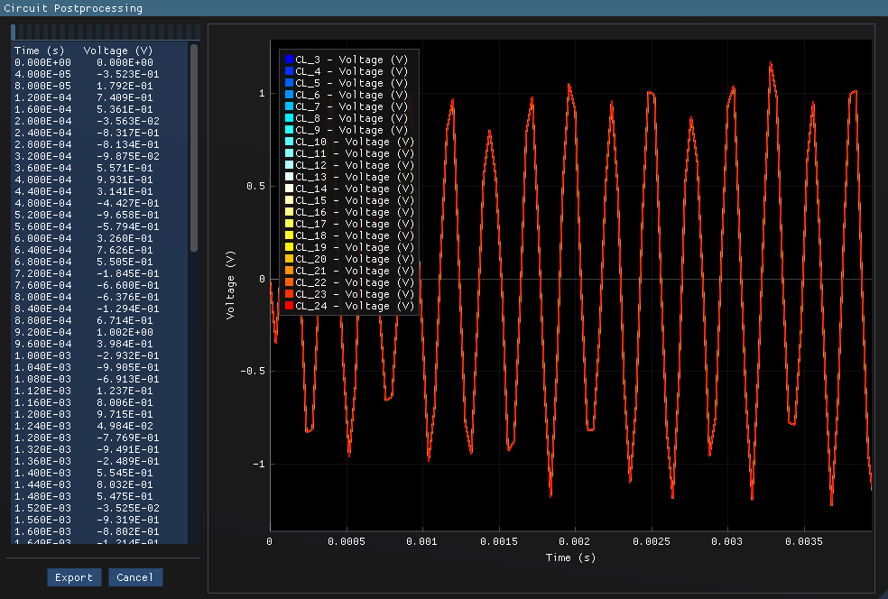
Voltage in the bus bars vs time plot during motor startup.
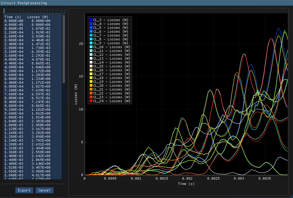
Joule loss in the bus bars vs time plot during motor startup.
An animation of the magnetic flux density distribution during motor operation is shown below.
Additional post-processing can be performed to extract more insights from the simulation data
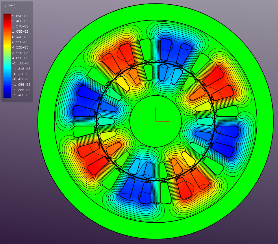
Vector Magnetic Potential (A)
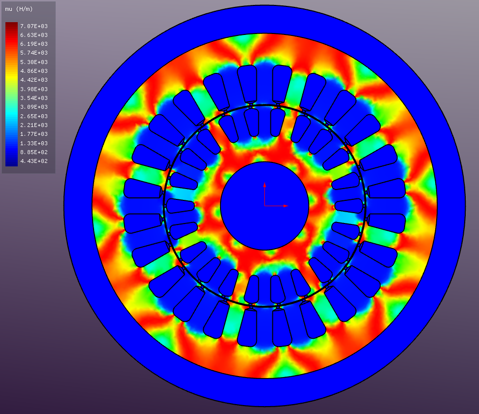
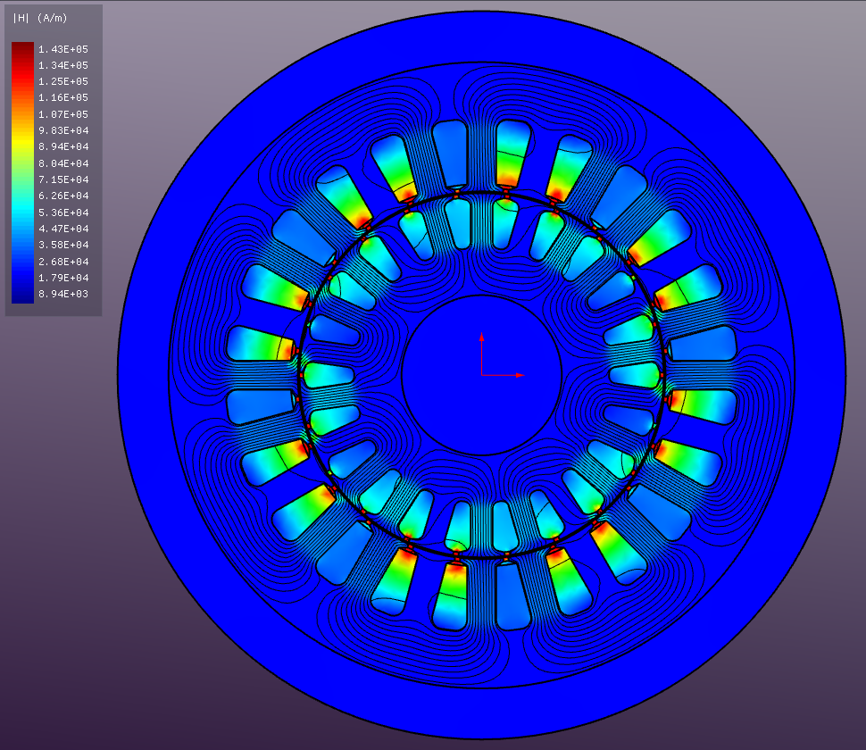
Absolute Magnetic Field Strength (H)
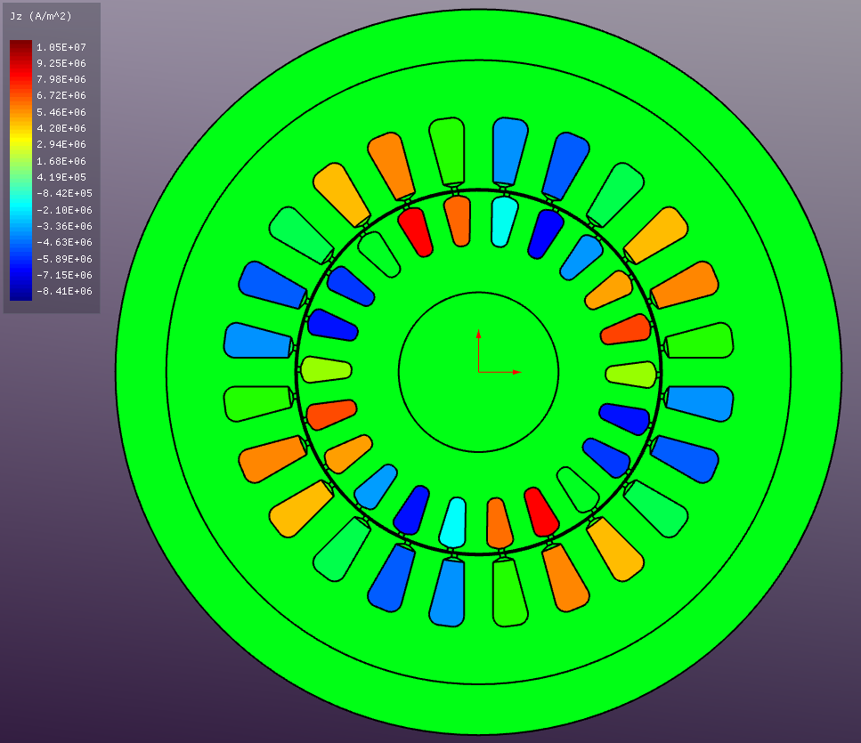
Current Density (J)
Relative Permeability (μ)