E05 — 18-slot / 16-pole surface-PM outrunner, 45 mm across, 20 000 rpm
PMSM - Outrunner · Surface-Mounted PM · 18 slots / 16 poles · 0.387 N·m at 20000 rpm · 90.4 % efficient · 3748 nodes · 55 s
What you need to run it: the Python API, the Machines module and Materials Pro. Opening the model and reading results that are already there never requires a licence. Materials Pro is needed only to fit the iron-loss coefficients from the shipped loss table. The machine itself does not need it.
At a glance
| Quantity | Value | Unit |
|---|---|---|
| Speed | 20000 | rpm |
| Electrical frequency | 2666.7 | Hz |
| Average torque | 0.387 | N·m |
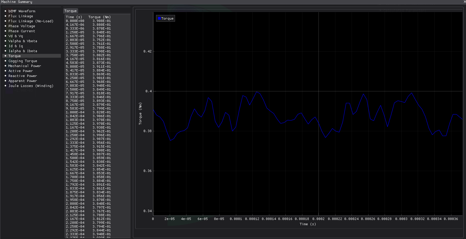
| Torque ripple | 6.9 | % |
| Cogging torque, peak-peak | 0.019 | N·m |
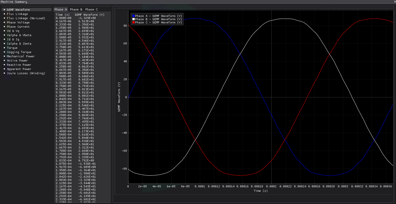
| Back-EMF, RMS | 65.2 | V |
| Mechanical power | 0.811 | kW |
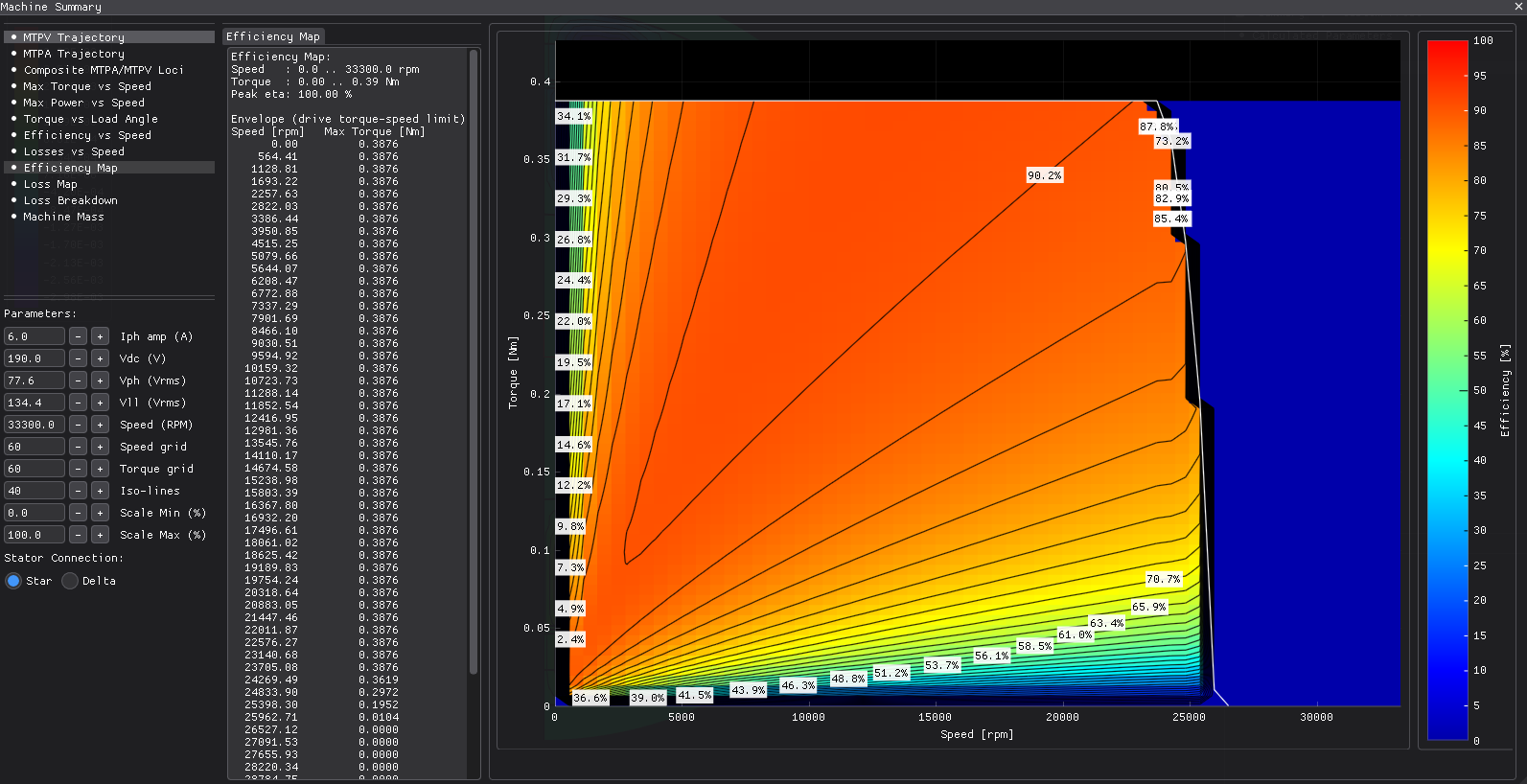
| Efficiency | 90.40 | % |
| Power factor | 0.997 | — |
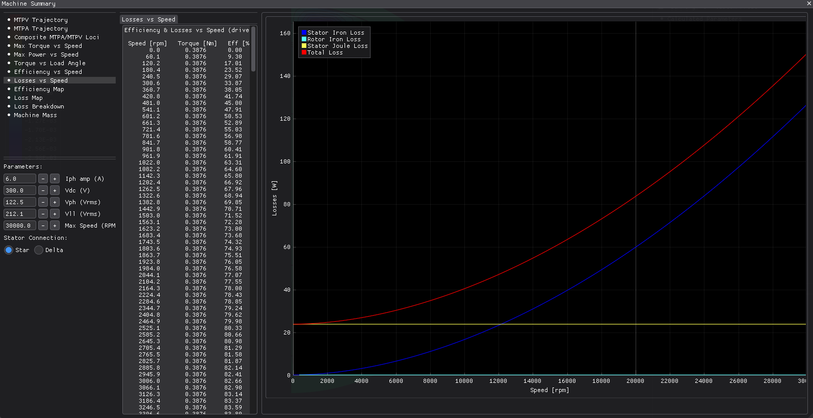
| Total losses | 86.2 | W |
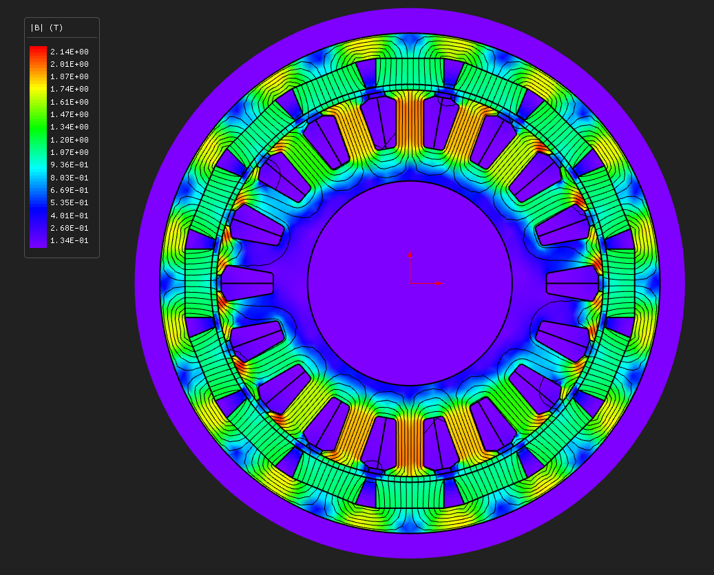
| Max B, stator tooth | 1.941 | T |
| Mesh | 3748 nodes, 6913 elements, P1 | — |
| Wall time, end to end | 55 | s |
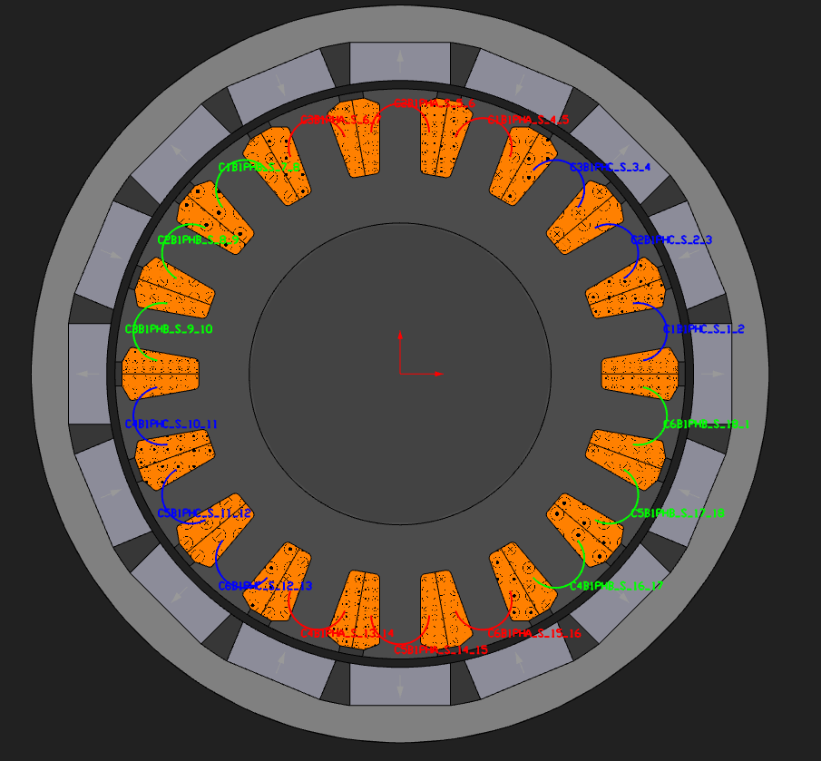
A small outrunner of the kind you find on a drone or an RC model: 45 mm outside diameter, 20 mm of stack, spinning at 20 000 rpm. The rotor is on the outside and the stator sits inside it, which turns every radius in the build inside out. It also runs at 2.67 kHz electrical, which makes it the example where iron loss, not copper loss, is the interesting number.
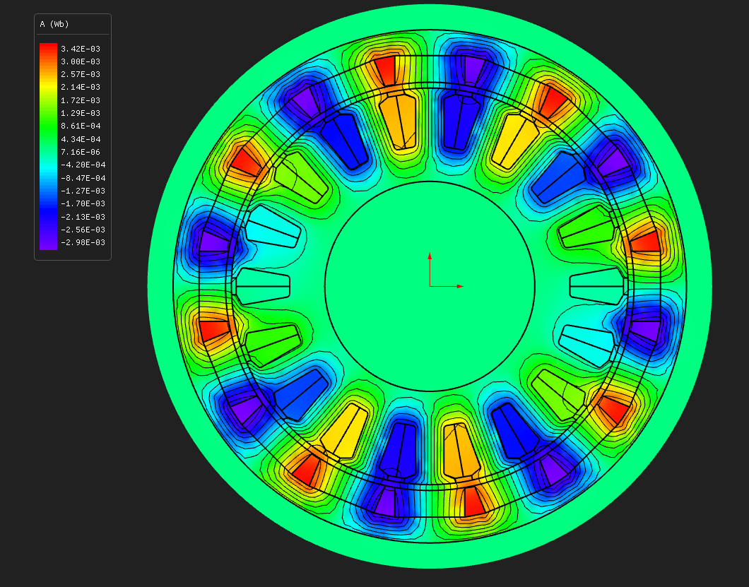
Half the machine is solved — nine slots and eight poles, closed with a periodic boundary, not an anti-periodic one, because the sector holds an even number of poles.
The design
Worked inward from the rotor's outside diameter, which is how an outrunner is actually specified:
| Layer | Radii (mm) | Set by |
|---|---|---|
| bore | 9.000 | derived: slot bottom − stator coreThickness |
| slot bottom | 12.000 | stator coreThickness 3 |
| stator iron OD | 17.000 | slotDepth 5, slotWidth 2.2, so stator OD 34 |
| stator sleeve | 17.0 → 17.2 | stator sleeveThickness 0.2 |
| air gap | 17.2 → 17.7 | airGap 0.5 |
| rotor sleeve | 17.7 → 18.0 | rotor sleeveThickness 0.3 |
| magnet | 18.0 → 20.5 | PMThickness 2.5, PMWidth 6 |
| rotor core | 20.5 → 22.5 | rotor coreThickness 2, giving 45.0 mm outside |
Three things about outrunner geometry that are not guessable
OD is the stator's gap-facing iron diameter — the tooth tips — not the outside of the
machine. The rotor grows outward from there.
The stator ID does nothing. On an outrunner the bore is derived as slot bottom minus the
back-iron thickness. Setting ID changes nothing and reading it back tells you nothing useful.
Move the bore with coreThickness instead.
The retaining sleeve grows outward from the iron OD into the gap, so it does not eat into the teeth. Do not set it to zero: a zero-thickness sleeve writes zero-length segments and the mesher fails on them. At 0.2 and 0.3 mm on a machine this small, that is a live risk.
Winding and materials
| Stator core | M-15 Steel, nonlinear BH |
| Rotor core (the can) | 1020_steel — mild steel, not a lamination |
| Magnets | N42SH, an SH grade, because 20 000 rpm in a small housing means a hot magnet |
| Winding | concentrated, double layer, one coil per tooth |
| Turns per coil | 10 (18 coils, six in series per phase) |
| Slot fill | 0.40 |
| End winding | 3 mm extension, resistance and inductance included |
The end-winding extension is short on purpose. A concentrated coil wraps a single tooth, so its overhang is about a tooth wide rather than a pole pitch.
q = 18 / (16 × 3) = 0.375, which sits inside the useful band for a fractional-slot concentrated winding, and the winding factor is 0.945.
Operating point
| Current | 6 A peak, pure q-axis |
| Speed | 20 000 rpm, so 2666.7 Hz electrical, a 375 µs period |
| Window solved | one electrical period, 90 steps, 4.17 µs each |
| Mesh | 0.4 mm maximum |
Ninety steps is set by the cogging, not by the fundamental. One electrical period is 45° mechanical, and this combination has 144 cogging events per turn, so an electrical period contains 18 cogging cycles. Ninety steps gives five samples each. Thirty-six steps would give two, which is the Nyquist limit and reads as noise.
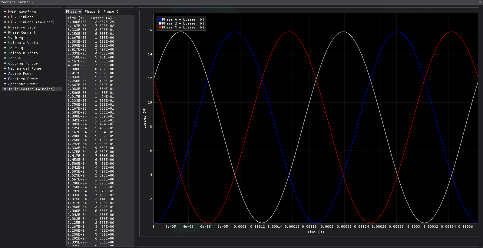
Six amps peak puts the current density at 12.7 A/mm², which a small air-blown outrunner can hold continuously. The machine solves happily at 12 A too, but then 25 A/mm² of copper loss buries the iron loss and the reason for the example disappears.
Iron loss
No material in the shipped library carries a specific-loss table, so this example brings its own and fits Steinmetz coefficients from it onto the stator core. It is the same representative 0.35 mm non-oriented grade E02 uses — about 2.6 W/kg at 50 Hz and 1.5 T — but carried out to 3 kHz, because a table that stops at 1 kHz has nothing to say about a machine running at 2.67 kHz and the fit would be extrapolating.
The table is generated from a known Steinmetz triple, so the fit has a right answer to be
checked against, and it returns it. Use the same route for real steel: a table of measured
points, fitIronLossCoefficients, then assign the coefficients to the region.
Running it
Open pmsm_outrunner_18s16p.nbl and press Solve. The solved field ships with this one, so you
can open it and look without solving anything.
From Python:
python build_pmsm_outrunner_18s16p.py             # build, solve, render, report
python build_pmsm_outrunner_18s16p.py --no-solve  # geometry and mesh only
About a minute and a half end to end, most of it not the field solve.
What to look at
The loss split. Iron loss is 44 % of the total here. On a machine running at 167 Hz, iron loss is a rounding error next to copper loss; on the same class of steel at 2.67 kHz it is the larger half of the budget. That is the whole point of this operating point, and it is the thing to remember when you scale a design up in speed.
L_d against L_q. They match to within a per cent, outer rotor or not. A surface-magnet rotor has no saliency and no reluctance torque, and the torque constant times the q-axis current accounts for the whole 0.34 N·m.
The power balance. It is checked as mechanical power plus copper loss against electrical input, and it closes to 0.02 %. Iron loss is deliberately left out of that sum: it is post-processing, integrated from the solved field afterwards and never fed back into the solve, so it cannot appear in an input computed from terminal voltages and currents. On a machine where iron loss is a few per cent of the input, charging it to the input turns a good check into a failing one for no physical reason.
What to trust, and what not to
The iron loss is honest for this steel, and this steel is not what you would build. The
thinnest lamination in the shipped library is M-15, and the fitted table is a representative
0.35 mm grade. A machine really built for 2.67 kHz would use a 0.20 or 0.10 mm grade and would
show materially less iron loss. Take the number as "what a 0.35 mm-class steel does here", not
as a prediction for the design as anyone would build it.
The rotor iron loss figure is not a claim either. The can is solid mild steel, and a Steinmetz lamination model has nothing true to say about eddy currents in a solid body. It reads near zero because the flux in an outrunner's can really is close to DC — which is why a solid can is buildable at all — but a real can at this frequency carries slot-harmonic eddy losses this model does not represent.
Cogging and torque ripple are at the noise floor. Refine the mesh from 0.4 to 0.25 mm and torque, back-EMF, tooth flux density and iron loss all move by about a tenth of a per cent, while the cogging peak-to-peak goes from 0.002 to 0.011 N·m and the ripple from 0.8 % to 3.4 %. Both stay under 4 % of rated torque in every run, which is the honest statement: this is a low-cogging combination and the residual is smaller than a mesh of this size can resolve across a 0.5 mm gap. Treat a change in either as meaningful only after re-reading this paragraph.
Try this next
--mesh-size 0.25— the refinement described above, at about twice the wall time.- Thin the stator back iron,
coreThickness3 → 2 mm. The bore opens from 9 to 10 mm at constant tooth geometry, which is what you do to fit a bigger shaft or bearing. Watch the yoke flux density climb as the yoke thins. - Halve the speed, 20 000 → 10 000 rpm at the same current. Torque is unchanged and the iron loss falls by roughly four times on the eddy term and two on the hysteresis term, which is the Steinmetz split made visible.
- Swap the magnet grade and watch the demagnetisation margin rather than the torque.
About these numbers
The dimensions are invented but plausible. A 45 mm outrunner at 20 000 rpm is a class of machine, not a particular product, and no measurement backs it. For accuracy, see the validation dossier.
More from this run