V14 — Sector vs full model; sliding band vs conforming mesh
Tier S - Self-consistent
Tier S (self-consistency) - priority P0
Reference frozen on 2026-08-14. Nabla 0.1.0,
solver licence mode enforcing,
run in 1229.0 s.
1. Problem
One machine, sixteen models of it, and no external reference anywhere.
Almost every machine result Nabla produces is computed on a sector and
carried by a sliding band. Both are exact constructions rather than
approximations - a periodic sector is the whole machine, and a band at
displacement theta is the mesh drawn at theta - so if either is wrong, it
is wrong silently and by an amount no convergence study can find. That is what
this case measures, and it is the reason it compares Nabla only against Nabla.
The machine is a 12-slot, 4-pole surface-PM motor with fully open slots:
| Quantity | Value |
|---|---|
| Slots / poles | 12 / 4 (1 slot per pole per phase) |
| Rotor core OD / magnet OD / bore | 25 / 28 / 30 mm |
| Slot bottom / stator OD | 40 / 50 mm |
| Magnet | Br = 1.2 T, mu_r = 1.05, spanning 80 % of the pole pitch |
| Iron | linear, mu_r = 2000, rotor and stator |
| Winding | single layer, full pitch, 30 turns per slot, phase belt A C B with alternating sign |
| Excitation | i_ph = 100 A * sin(2*theta_m - 120 deg + phi_ph), i.e. on the q axis |
| Axial length | 100 mm |
Twelve slots and four poles is the smallest combination in which a 90-degree window holds a whole number of slots (3) and a whole pole, and a 180-degree window a whole pole pair - and the windows are cut at tooth centres, so no sector edge ever passes through a slot. Open slots are deliberate: they give the airgap field the strongest slot harmonics a stator can produce, which is what the periodic boundary and the sliding band have to carry correctly.
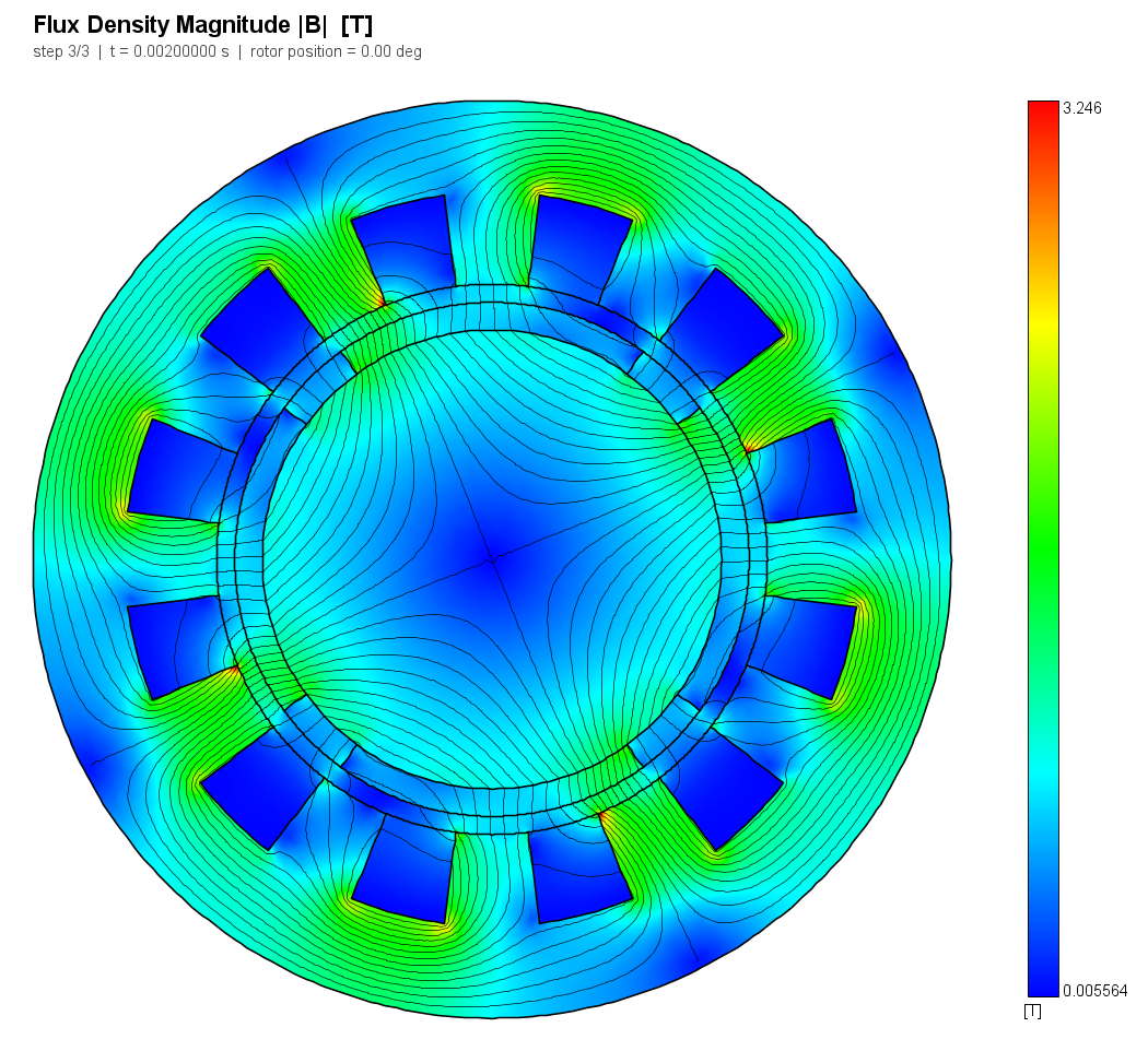
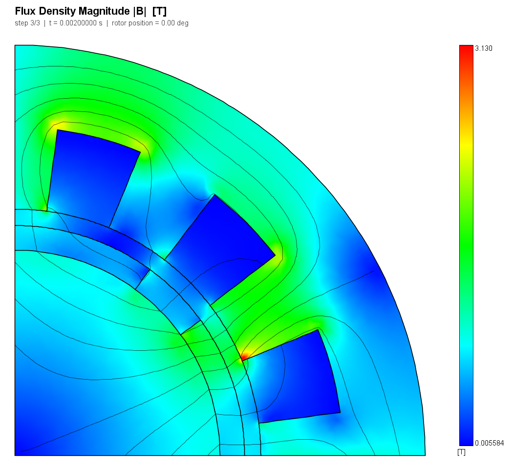
The sixteen sub-models:
| Sub-models | Window | Sides | Rotor carried by | Load |
|---|---|---|---|---|
full_a0 .. full_a3 |
360 deg | - | drawn at 0, 22.5, 45, 67.5 deg | both |
pair_a0 .. pair_a3 |
180 deg | periodic | drawn at the same four angles | both |
pole_a0 .. pole_a3 |
90 deg | anti-periodic | drawn at the same four angles | both |
band_load |
90 deg | anti-periodic | averaging sliding band, +90 deg/s, 40 steps | rated |
band_noload |
90 deg | anti-periodic | the same sweep | none |
band_rev |
90 deg | anti-periodic | the same sweep backwards | rated |
two_mover |
90 deg | anti-periodic | rotor +45 deg/s and stator -45 deg/s, both band rings moving | none |
"Both" means each static sub-model is solved twice in one run: a custom current waveform is zero at record 1 and at the rated value at record 2, so the same mesh yields the no-load field (magnets alone, for cogging and back-EMF) and the loaded one (for torque). Nothing in the model has a time derivative - linear iron, no eddy currents, no circuit - so every record is a magnetostatic solve at its own excitation, and "transient" here means nothing more than "several of them".
2. Reference
There is none, and that is the claim. See the case's reference notes for the argument in full; in short, the four legs compare things that are constructions of one another:
- Periodicity. A field with
p-fold symmetry satisfiesA(theta + 2*pi/N) = ±A(theta)exactly, so eliminating a periodic pair's slave nodes is an identity. The two sectors must reproduce the 360-degree model to the accuracy of the meshes and nothing else. - Band vs conforming. The band's interpolation constraint ties the moving
ring to the stationary one after shifting it by the relative angle. If that
is right, the answer is a conforming mesh's answer - up to the one stated
difference, that the 10 um annulus between the rings is unmeshed and is
therefore missing from the magnetic circuit (
band_gap_deficit_frac= +0.21 % of it). - Band-position invariance. On a 4-sector model,
+thetaand-(90 - theta)are the same physical position, reached by shifting the ring in opposite directions and wrapping. - Two movers against one. The multiple-motion-zone specification §13.1: a band is driven by the relative displacement of its two rings, so +45 and -45 deg/s is the same band as 90 deg/s against a stator at rest.
The reference for every judged row is therefore exactly zero deviation, and the two profile rows take the conforming (respectively single-mover) run as their reference array. Tolerances are the validation plan V14's: 0.5 % for the periodicity and band-position rows, 1 % for band vs conforming and for the two-mover pair.
3. Nabla model
Built entity by entity through nabla_api from geometry.json, which is the
only place any number about the machine is written. build.py takes the window
as a parameter: the rotor's magnets and spacers are generated as intervals on
the circle and clipped into it, the stator's slots and tooth faces likewise, and
the sector's two straight sides are drawn one segment per layer so that no
layer arc ever ends in the middle of a boundary segment (V04's T-junction).
Three details decide whether the comparison means anything:
- The same node spacing on every shared boundary. Every full-circle arc is subdivided into a count rounded up to a multiple of four, and each window takes that count times its own fraction of the circle. The 90, 180 and 360-degree models therefore carry identical node spacing everywhere, and a difference between them is not a difference of discretisation. The airgap is meshed at 0.25 mm - eight element layers across the 2 mm gap.
- The annulus between the band rings is a hole, never a region (rule M16).
Mesher.GenerateMeshrunsMotionBandMeshCheckon every mesh built here. - One torque instrument for all sixteen.
T = L r^2/mu0 * INT Bn*Bt dthetaon seven circles between 28.9 and 29.5 mm, averaged, times the number of sectors. Seven rather than one because a single circle reads the mesh as much as the field; the stator side of the gap because it is the only part that exists in every sub-model. Nabla's own band torque is read as well, where there is a band, and published beside it.
| Sub-model | Element order | Nodes | Elements |
|---|---|---|---|
full_a0 |
P1 | 23952 | 47588 |
full_a1 |
P1 | 23998 | 47697 |
full_a2 |
P1 | 23960 | 47617 |
full_a3 |
P1 | 23944 | 47582 |
pair_a0 |
P1 | 11995 | 23729 |
pair_a1 |
P1 | 12028 | 23791 |
pair_a2 |
P1 | 12050 | 23831 |
pair_a3 |
P1 | 12095 | 23928 |
pole_a0 |
P1 | 6034 | 11883 |
pole_a1 |
P1 | 6026 | 11864 |
pole_a2 |
P1 | 6031 | 11873 |
pole_a3 |
P1 | 6004 | 11823 |
band_load |
P1 | 6055 | 11567 |
band_noload |
P1 | 6055 | 11567 |
band_rev |
P1 | 6055 | 11567 |
two_mover |
P1 | 6055 | 11567 |
4. Results
| Quantity | Metric | Nabla | Reference | Error | Tolerance | Verdict |
|---|---|---|---|---|---|---|
periodicity_torque_max_rel |
abs | 0.00354643 - | 0 - | 0.003546 | 0.005 | PASS |
periodicity_flux_max_rel |
abs | 6.9331e-05 - | 0 - | 6.933e-05 | 0.005 | PASS |
periodicity_bemf_max_rel |
abs | 4.91995e-05 - | 0 - | 4.92e-05 | 0.005 | PASS |
band_vs_conforming_torque_max_rel |
abs | 0.00431275 - | 0 - | 0.004313 | 0.01 | PASS |
band_vs_conforming_flux_max_rel |
abs | 0.00167177 - | 0 - | 0.001672 | 0.01 | PASS |
band_vs_conforming_Bn_T |
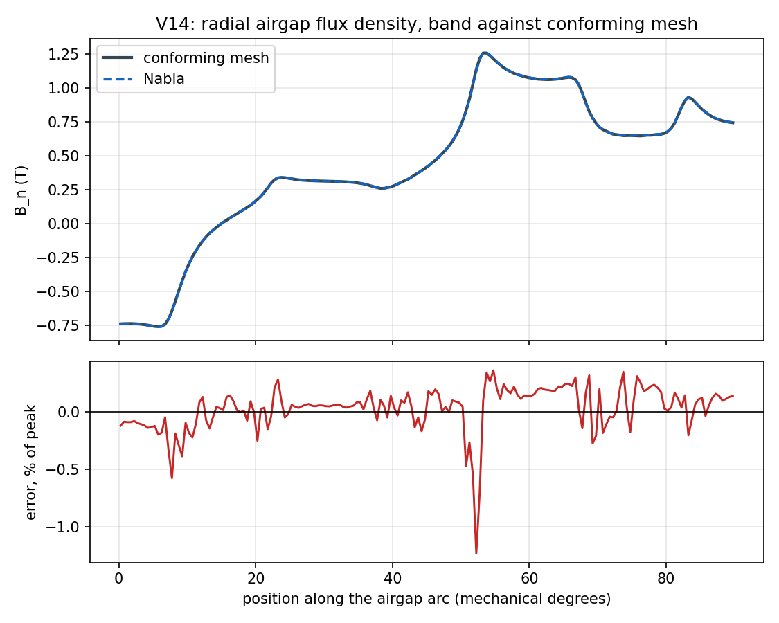
profile | min=-0.7631, max=1.261, rms=0.6865 T | min=-0.7606, max=1.257, rms=0.6856 T | L2 +0.357 %, max +1.233 % | L2 1.000 %, max 2.000 % | PASS |
band_position_invariance_torque_max_rel |
abs | 1.37191e-14 - | 0 - | 1.372e-14 | 0.005 | PASS |
two_mover_vs_single_torque_nrmsd |
abs | 1.30433e-06 - | 0 - | 1.304e-06 | 0.01 | PASS |
two_mover_vs_single_Bn_T |
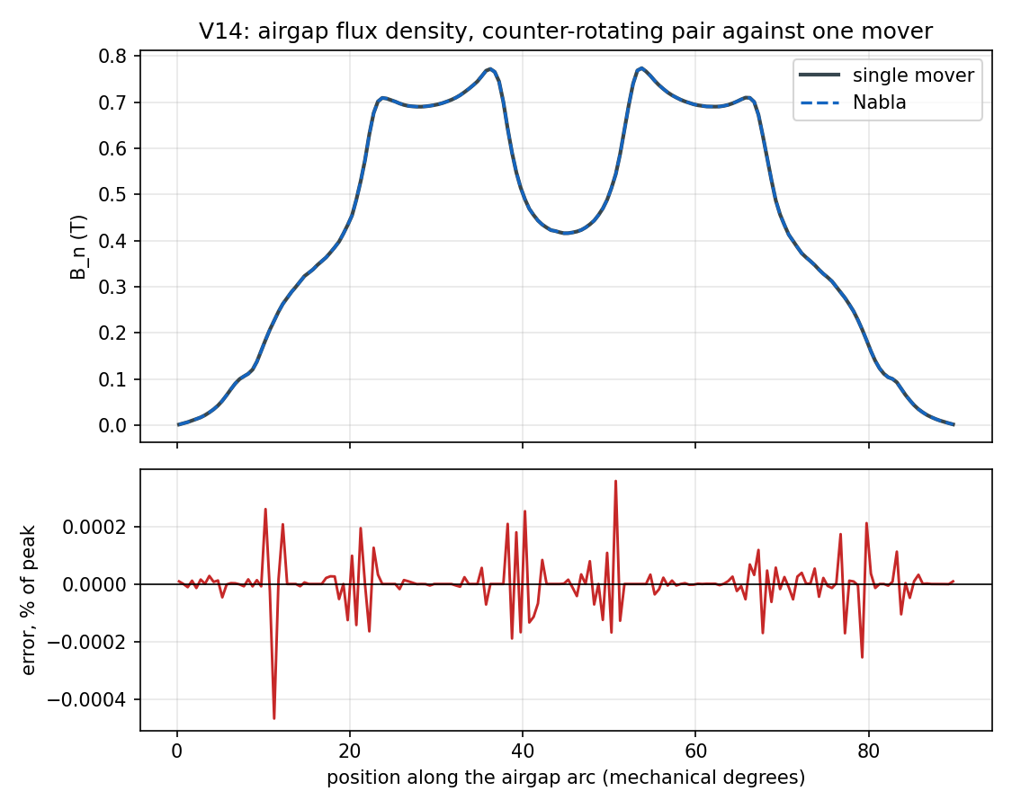
profile | min=0.001205, max=0.774, rms=0.5025 T | min=0.001205, max=0.774, rms=0.5025 T | L2 +0.000 %, max +0.000 % | L2 1.000 %, max 2.000 % | PASS |
phase_current_max_err_A |
abs | 4.61853e-14 A | 0 A | 4.619e-14 | 0.001 | PASS |
periodicity_cogging_max_abs_Nm |
report | 0.0691166 N.m | - N.m | - | - | REPORT |
band_vs_conforming_cogging_max_abs_Nm |
report | 0.0435507 N.m | - N.m | - | - | REPORT |
band_own_torque_vs_contour_max_rel |
report | 0.00118838 - | - - | - | - | REPORT |
band_full_sector_return_torque_rel |
report | 1.03823e-05 - | - - | - | - | REPORT |
band_gap_deficit_frac |
report | 0.00205882 - | - - | - | - | REPORT |
torque_instrument_spread_load |
report | 0.00945129 - | - - | - | - | REPORT |
torque_instrument_spread_noload_Nm |
report | 0.115368 N.m | - N.m | - | - | REPORT |
band_mid_gap_Bn_l2 |
report | 0.00357452 - | - - | - | - | REPORT |
band_near_ring_Bn_l2 |
report | 0.00618417 - | - - | - | - | REPORT |
band_near_ring_Bn_T |
report | (series) | - | - | - | REPORT |
band_near_ring_Bn_conforming_T |
report | (series) | - | - | - | REPORT |
band_own_torque_Nm |
report | (series) | - | - | - | REPORT |
bemf_peak_full_V |
report | 37.8253 | - | - | - | REPORT |
bemf_peak_pair_V |
report | 37.8272 | - | - | - | REPORT |
bemf_peak_pole_V |
report | 37.8247 | - | - | - | REPORT |
cogging_band_Nm |
report | (series) | - | - | - | REPORT |
cogging_full_Nm |
report | (series) | - | - | - | REPORT |
cogging_pair_Nm |
report | (series) | - | - | - | REPORT |
cogging_pole_Nm |
report | (series) | - | - | - | REPORT |
flux_linkage_A_full_Wb |
report | (series) | - | - | - | REPORT |
flux_linkage_A_pair_Wb |
report | (series) | - | - | - | REPORT |
flux_linkage_A_pole_Wb |
report | (series) | - | - | - | REPORT |
mesh_nodes_full |
report | 23952 | - | - | - | REPORT |
mesh_nodes_pair |
report | 11995 | - | - | - | REPORT |
mesh_nodes_pole |
report | 6034 | - | - | - | REPORT |
torque_band_Nm |
report | (series) | - | - | - | REPORT |
torque_band_reverse_Nm |
report | (series) | - | - | - | REPORT |
torque_full_Nm |
report | (series) | - | - | - | REPORT |
torque_pair_Nm |
report | (series) | - | - | - | REPORT |
torque_pole_Nm |
report | (series) | - | - | - | REPORT |
torque_single_mover_Nm |
report | (series) | - | - | - | REPORT |
torque_two_mover_Nm |
report | (series) | - | - | - | REPORT |
periodicity_cogging_max_abs_Nm: Published without a verdict, by declaration: the seven-circle torque instrument has a ~20 % radius spread on cogging (a peak cogging integrand two orders of magnitude above the net result), so a tolerance on this row would be measuring the instrument. It is reported beside torque_instrument_spread_noload for exactly that reasonband_vs_conforming_cogging_max_abs_Nm: The same quantity for the band against the conforming mesh, and published on the same groundsband_own_torque_vs_contour_max_rel: Nabla's own band-gap-layer (Arkkio) torque against this case's seven-circle contour average, at the four angles of the loaded band sweep. Reported rather than judged: it compares two instruments on ONE solution and so says nothing about the sector, the band or the domain - but it is the number that says whether the instrument this case built is the one the product reportsband_full_sector_return_torque_rel: Torque at the end of the sweep (rotor one full sector on, currents half an electrical period on) against the start. The band has to walk the whole sector and wrap to get there, so this is the cyclic wrap in cyclicShiftArc measured on its ownband_gap_deficit_frac: The unmeshed annulus between the two band rings as a fraction of the magnetic circuit it is missing from (mechanical gap plus magnet thickness over its recoil permeability). Arithmetic on the geometry, not a measurement: it is the systematic bias every band-vs-conforming row is read throughtorque_instrument_spread_load: Worst spread of the seven probe circles about their mean at the load point, over every static sub-model. This case's own measurement uncertainty on every loaded torque rowtorque_instrument_spread_noload_Nm: The same spread at no load, in N.m rather than as a ratio because the cogging mean passes through zero twice over these four angles. Compare it against cogging_full_Nm, whose peak is about 0.7 N.m: the instrument's uncertainty is a large fraction of the quantity, which is the reason the cogging rows carry no verdictband_mid_gap_Bn_l2: Relative L2 of the band's airgap field against the conforming mesh's at r = 29.2 mm - the same number the judged band_vs_conforming_Bn_T row reports, published as a scalar so it can be set beside the near-ring oneband_near_ring_Bn_l2: The same comparison 0.09 mm outside the stationary band ring instead of 0.79 mm. Reported, never judged: a conforming mesh has no ring to be near, so there is no tolerance to hold the band to here. It is the measurement behind the rule this case had to adopt for its own instrument - keep a post-processing contour clear of a band ringband_near_ring_Bn_T: extracted but not frozen in expected.json - reported onlyband_near_ring_Bn_conforming_T: extracted but not frozen in expected.json - reported onlyband_own_torque_Nm: extracted but not frozen in expected.json - reported onlybemf_peak_full_V: extracted but not frozen in expected.json - reported onlybemf_peak_pair_V: extracted but not frozen in expected.json - reported onlybemf_peak_pole_V: extracted but not frozen in expected.json - reported onlycogging_band_Nm: extracted but not frozen in expected.json - reported onlycogging_full_Nm: extracted but not frozen in expected.json - reported onlycogging_pair_Nm: extracted but not frozen in expected.json - reported onlycogging_pole_Nm: extracted but not frozen in expected.json - reported onlyflux_linkage_A_full_Wb: extracted but not frozen in expected.json - reported onlyflux_linkage_A_pair_Wb: extracted but not frozen in expected.json - reported onlyflux_linkage_A_pole_Wb: extracted but not frozen in expected.json - reported onlymesh_nodes_full: extracted but not frozen in expected.json - reported onlymesh_nodes_pair: extracted but not frozen in expected.json - reported onlymesh_nodes_pole: extracted but not frozen in expected.json - reported onlytorque_band_Nm: extracted but not frozen in expected.json - reported onlytorque_band_reverse_Nm: extracted but not frozen in expected.json - reported onlytorque_full_Nm: extracted but not frozen in expected.json - reported onlytorque_pair_Nm: extracted but not frozen in expected.json - reported onlytorque_pole_Nm: extracted but not frozen in expected.json - reported onlytorque_single_mover_Nm: extracted but not frozen in expected.json - reported onlytorque_two_mover_Nm: extracted but not frozen in expected.json - reported only
5. Discussion
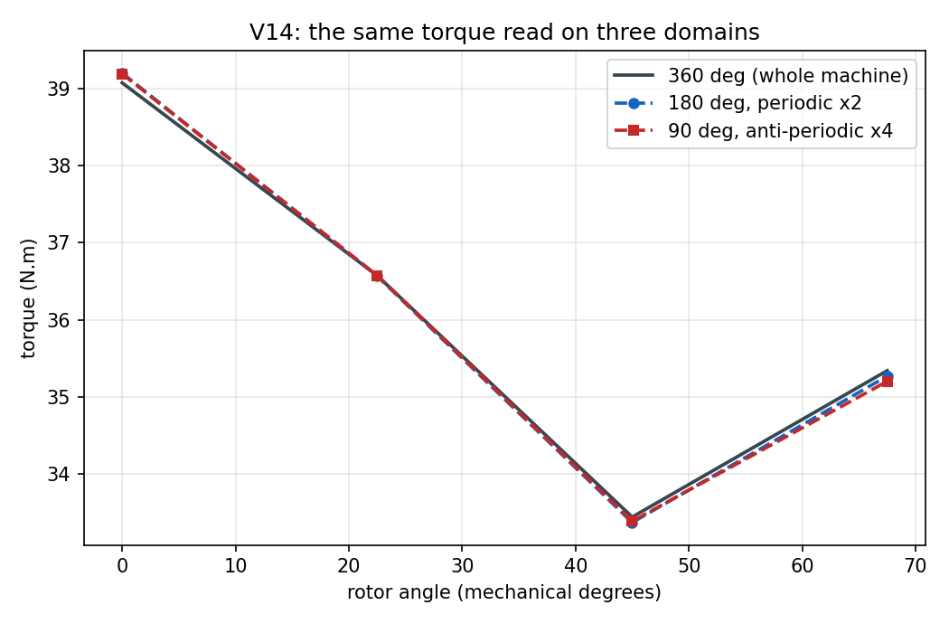
The sector is free. Torque, phase flux linkage and back-EMF agree across 360, 180 and 90 degrees to +0.35 %, 0.0069 % and 0.0049 % against a 0.5 % tolerance - which is to say the master/slave elimination costs nothing measurable, and a machine designer who models one pole of a symmetric machine is not trading accuracy for speed. The 90-degree model has a quarter of the nodes of the 360-degree one and returns the same numbers.
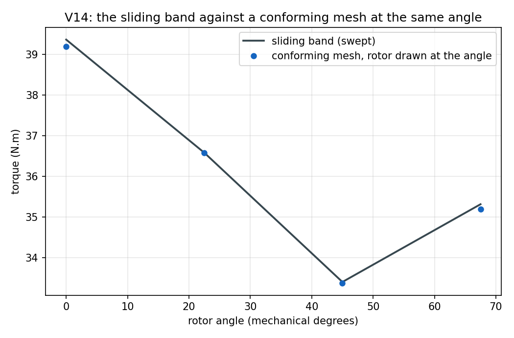
The band costs about what its hole costs. The swept band reproduces the conforming mesh drawn at the same angle to +0.43 % on torque and +0.17 % on flux linkage, against a 1 % tolerance and with a known systematic bias of +0.21 % from the unmeshed annulus. The airgap field is the sharper test - a profile, not a scalar, so nothing averages out - and it agrees to +0.357 % in L2 with a worst point at +1.233 %.
The band's own error is local to its ring. The same comparison sampled 0.09 mm outside the stationary ring instead of 0.79 mm rises from +0.36 % to +0.62 % in L2 - published without a verdict, because a conforming mesh has no ring to be near and there is no tolerance to hold the band to there. Measured while the case was being built, the ratio is larger still off the load point: at 22.5° the near-ring profile is 0.93 % against 0.40 % one element further out, and the error is flat in radius beyond that rather than decaying, so it is the ring's own interpolation and not a boundary layer. The practical rule that follows is the one this case had to adopt for its own instrument: keep a post-processing contour two elements clear of a band ring, and read torque from the middle of the gap rather than beside the band.
A defect found while building the case, worth naming because it is silent.
The motion zone was first drawn out to 29.0 mm - inside the airgap but outside
the stationary band ring at 28.41 mm. Everything about that model was healthy:
it solved, its torque and flux linkage agreed with the conforming mesh to 0.2 %,
and Nabla's own band torque agreed with the contour. But the airgap field
sampled between the ring and the zone edge disagreed with the conforming mesh by
80 %, because the post-processing transform rotates a moving part's field
into the lab frame and it had been told that a stretch of stationary air was
part of the rotor. The zone radius is a model input with no default and no
check, and the symptom appears only in a field probe placed in the wrong 0.6 mm
of the model. motion_zone_radius() in build.py now derives it from the two
band radii, and the rule it states is the finding: a motion zone must end
between the two rings of its band.
A second one, in the same code path, that costs one record out of forty-one.
Results.interpolateAngle returns early once the time passes the motion
profile's last point - and returns without carrying the accumulated position
forward, though its own comment says it should. A constant-speed profile is
naturally written [[0, speed], [t_end, speed]] with t_end the end of the run
(it is what V11 writes, and what this case wrote first), so the final record
of such a model has its moving parts back at their as-drawn angle: the
rendered field snaps back for one frame, and a probe inside a moving zone reads
the untransformed solution. Here it turned an exact two-mover agreement into a
35 % failure on the strength of record 40 alone, while records 0 to 39 were
identical to the last digit. The solver integrates the profile itself and is
unaffected, which is why nothing else has ever noticed. build.py now ends
every profile at twice the run duration. Both findings are written up in
case V14.
Both directions of the wrap agree. Reaching a rotor angle by turning the
band backwards a whole sector gives the same torque as reaching it forwards to
1.4e-14 - round-off, not agreement. That is the right answer, and it is
worth saying why: the two displacements differ by exactly one sector, which the
anti-periodic wrap maps onto itself, so the two runs assemble the same linear
system and the identity is exact rather than approximate. If the seam logic
mishandled either direction it would not be, and the row would not be small - it
would be wrong. Walking the band right round its sector to the far end of the
sweep reproduces the starting torque to 1.0e-5; that one is a genuine
numerical difference, because the rotor has passed through forty band positions
and the currents have advanced half an electrical period to get there. Both
exercise cyclicShiftArc's seam handling on a sector band - the same code whose
full-circle path is the open defect case V04 finding F3 records.
Two movers are one mover. The counter-rotating pair, with both band rings
marked moving and each naming its own motion, reproduces the single-mover sweep
to 1.3e-6 of the cogging peak over all 41 records, and its airgap field at 45 degrees of relative displacement matches
to +0.000 % in L2 - that is 180 field samples
agreeing to every digit, which is what it should be: both models hand the band
the same relative displacement, so the constraint sets and the assembled systems
are the same. The multiple-motion-zone specification §13.5 pinned that path with two
hand-edited .mfs A/B runs; this is the same claim made from the public API, on
a machine, and judged. What the leg really tests is the frame bookkeeping
around it - which is where it found both of the defects above, since it is the
only sub-model in the dossier whose stator moves.
What the instrument itself is worth. The seven probe circles disagree with
each other by +0.95 % of the loaded
torque, and by 0.115 N.m at no load -
against a cogging peak of about 0.69 N.m, so a sixth of the quantity being
measured. That is the whole reason the cogging rows in the table carry no
verdict: at no load the integrand Bn*Bt is two orders of magnitude above the
net result, so a single-circle Maxwell-stress torque reads the mesh
(case V05 finding F2 measured a 2.3x radius dependence on exactly this). The cogging
agreement between domains is nevertheless better than the instrument's own
spread - 0.069 N.m across the three windows, and 0.044 N.m between the band and
the conforming mesh - which is reported and left at that.
Nabla's own band-gap-layer (Arkkio) torque and this case's seven-circle average
agree to +0.12 % on the loaded sweep,
so the instrument built here and the one the product reports are the same
instrument.
6. Limitations
- Nothing here says the answers are right. A machine whose torque is 5 % wrong in all sixteen sub-models passes this case, and should: V05, V11 and V15 are where the physics is judged against FEMM, an analytic induction motor and three independent force methods. V14 validates the machinery those cases rest on.
- The 360-degree models carry no band. A non-zero sliding-band displacement on a full-circle band is a known defect (case V04 finding F3: the answer stops depending on the displacement), so the full-circle models here are given their rotor angle by being drawn at it. What this case therefore does not test is a band on a full 360-degree model - and until F3 is fixed, that configuration should not be used.
- Linear iron, 1st-order elements, planar 2D, magnetostatic. No BH curve, no eddy currents, no circuit, no P2 mesh, no skew, no axisymmetric band. The periodicity claim in particular is made for a linear problem; a nonlinear one adds a Newton loop whose per-domain convergence path is not identical.
- One machine, one slot/pole combination, four rotor angles. A fractional slot machine, whose smallest symmetric sector is not a pole, is not covered.
- The two-mover leg is at no load. With the stator turning, a stator-frame current would have to be re-derived, and the comparison would be about that derivation rather than about the band.
- Cogging torque rows carry no verdict. Declared in
expected.json, for the instrument reason above - not because they disagreed.
7. Reproduce
cd validation
python -m harness.run_case V14
Needs triangle.exe and a licensed solver (NABLA_LICENSE); the two_mover
sub-model uses a second motion zone, which is a licensed feature. The sixteen
models are built, solved and read one at a time - only one Nabla model may be
live in a process - and every one of them is published under
artifacts/models/.
Changelog
No entry: the reference values and tolerances are as first frozen.